
The connector feels cool on an open bench, then runs warmer once it is inside the dock. That difference does not necessarily mean the wrong contact was chosen. The enclosure, connected board, cable and operating load all affect the conditions around the interface.
A magnetic connector temperature rise test should assess the selected connection under defined current and ambient conditions. CTP offers round magnetic pairs, custom modules, multi-contact cables and compact DC interfaces for different product arrangements. Their value is the choice of structures that can be developed around your device, with a validation plan matched to the supplied assembly.
A temperature-rise result should describe the connector inside its intended assembly
Ask what is carrying the current and what surrounds it. A loose connector pair, a receiver mounted on a PCB and a finished cable connected inside a small enclosure are different specimens. If the buying decision concerns the installed assembly, the assessment needs to represent the parts and environment that matter to that assembly.
The public description of IEC 60512-5-1 identifies temperature rise as a connector current-carrying-capacity test. It does not supply one universal acceptance limit for every custom magnetic interface. The applicable conditions and criteria belong to the selected product and project requirements.
A five-contact round pair offers a different thermal and mounting arrangement
Our five-contact round magnetic pair, CTP-MPC-5P-RD-HT-A01, is a product route for equipment whose connection needs review for elevated operating temperatures or thermal cycling. It combines a round mating form with five assigned contact positions.
The selected materials, installed position and electrical allocation determine the actual requirement. The product name should not be treated as an unlimited temperature rating. For a compact heated instrument, the useful discussion includes the heat already present in the enclosure before current is added to the connector path.
A custom module brings the board-side connection into the review
A module should be assessed with its supplied board arrangement
The CTP custom five-contact module, catalogue reference CTP-P3928, offers a module-level route rather than an isolated loose contact. Where the selected supply includes board-side components, those parts and their terminations need to be represented in the sample definition.
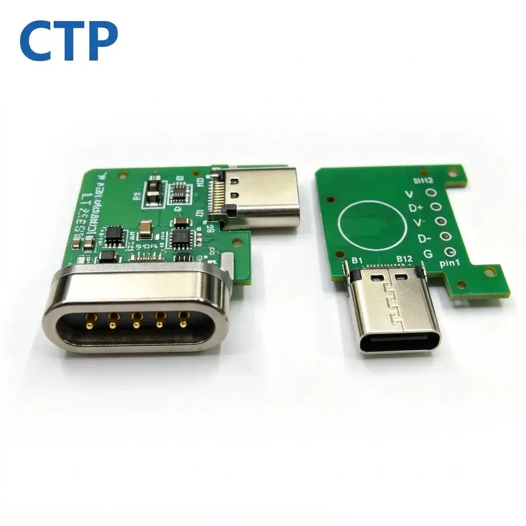
This can be useful for an OEM that wants to develop the connection and its receiving electronics as a coordinated physical assembly. It also makes the test boundary more important: the result should state whether it includes the module board and the final termination, rather than imply they have no influence.
On a board-mounted sample, note where the temperature sensor is placed relative to the contact and its termination. Nearby board traces or components can contribute heat, while the board itself can carry heat away. For the six-contact cable, the attached conductors create a different surrounding structure again. Keeping those distinctions visible helps the buyer compare a complete module with a finished lead fairly. It also supports a more useful development discussion with us: whether the connection should remain a board-level module, move to a cable format or use a compact pair installed elsewhere in the enclosure.
A six-contact cable includes conductors as well as mating contacts
Our six-contact dual-row magnetic cable, CTP-MCC-6P-DR-A17, uses a compact three-plus-three contact arrangement and a separate device-side mate. It gives the project team another contact layout within a complete cable format.
For a desktop charging dock, the lead may pass through a small opening before reaching the source connection. Conductor choice, termination and cable routing should be reviewed with the magnetic interface. Six available contacts do not mean six identical power paths, and the total current capability cannot be inferred by simply counting contacts.
A two-contact DC interface keeps the power path easy to identify
The CTP two-contact magnetic DC connector, catalogue reference CTP-P4269, provides a different starting structure for a defined power connection. For a product using a supply-and-return pair, the two paths and their terminations can be identified clearly in the drawing.
That simplicity is useful when the device does not need a larger multi-function interface. The selected cable or board connection still needs to carry the intended load under the agreed conditions. A compact connector should be approved as part of its complete power path, rather than selected solely because its catalogue description names a current value.
For example, a small desk accessory and an enclosed industrial controller may both use two electrical paths while presenting very different ambient and cooling conditions. The same contact count does not make their temperature-rise results directly interchangeable.
Compare thermal results after the current and temperature have settled
A short reading taken immediately after power is applied may not represent the later operating condition. Harwin’s explanation of current ratings describes monitoring ambient conditions and allowing the temperature to stabilise during testing. The exact dwell and acceptance requirements should follow the agreed test plan.
For supplier review, keep the sample configuration, electrical allocation, applied load, ambient condition and measuring locations with the result. If the product enclosure changes, decide whether that change affects the condition you previously approved.
Our connector current-derating guide adds context on relating a thermal assessment to the current requirement of the finished device.
CTP’s custom development route connects product structure, materials, manufacturing and project-specific validation. Our manufacturing and engineering information explains that scope. Bring the actual installed arrangement into the review, and the temperature discussion can guide a useful connector choice instead of relying on a reassuring label.