A handheld terminal may sit neatly in a dock until the cable is connected. Then the lead pushes against the wall, crosses the place where the operator grips the device, or makes the cradle rock on the counter. The connector can be electrically suitable and still leave the product feeling unfinished.
Handheld terminal charging dock cable routing works best when the cable exit, mating direction and board location are chosen together. Our CTP range includes slim multi-contact cable heads, round side-exit interfaces, USB-C-ended assemblies and right-angle board connectors. Each gives the dock designer a different way to keep the connection out of the user’s working space.
Start the dock cable route at the operator’s hand
Think about how the terminal leaves the cradle. A retail operator may lift it forward with one hand. A technician may pull it sideways from a shallow desktop holder. A cable that crosses either movement can become an irritation even if it has enough overall length.
Mark that movement on the dock layout before fixing the charging face. Then follow the lead to its source connection. The useful route needs room for the connector head, the cable transition and any bend near the enclosure. A universal bend-radius number is not appropriate; it depends on the selected cable construction.
A slim twelve-contact head can follow a narrow docking edge
The CTP twelve-contact slim magnetic cable, CTP-MCC-12P-SR-A01, has a rectangular head with twelve contacts in one linear row. It provides a distinct option where the interface needs several assigned electrical paths along a narrow edge.
For a terminal dock that combines charging with identification or control functions, that row can be discussed as a single interface rather than a collection of separate plugs. The actual functions still come from the approved circuit and wiring. Twelve contacts do not establish a particular communication protocol or charging capability by themselves.
A side-exit magnetic cable can turn the route away from the grip
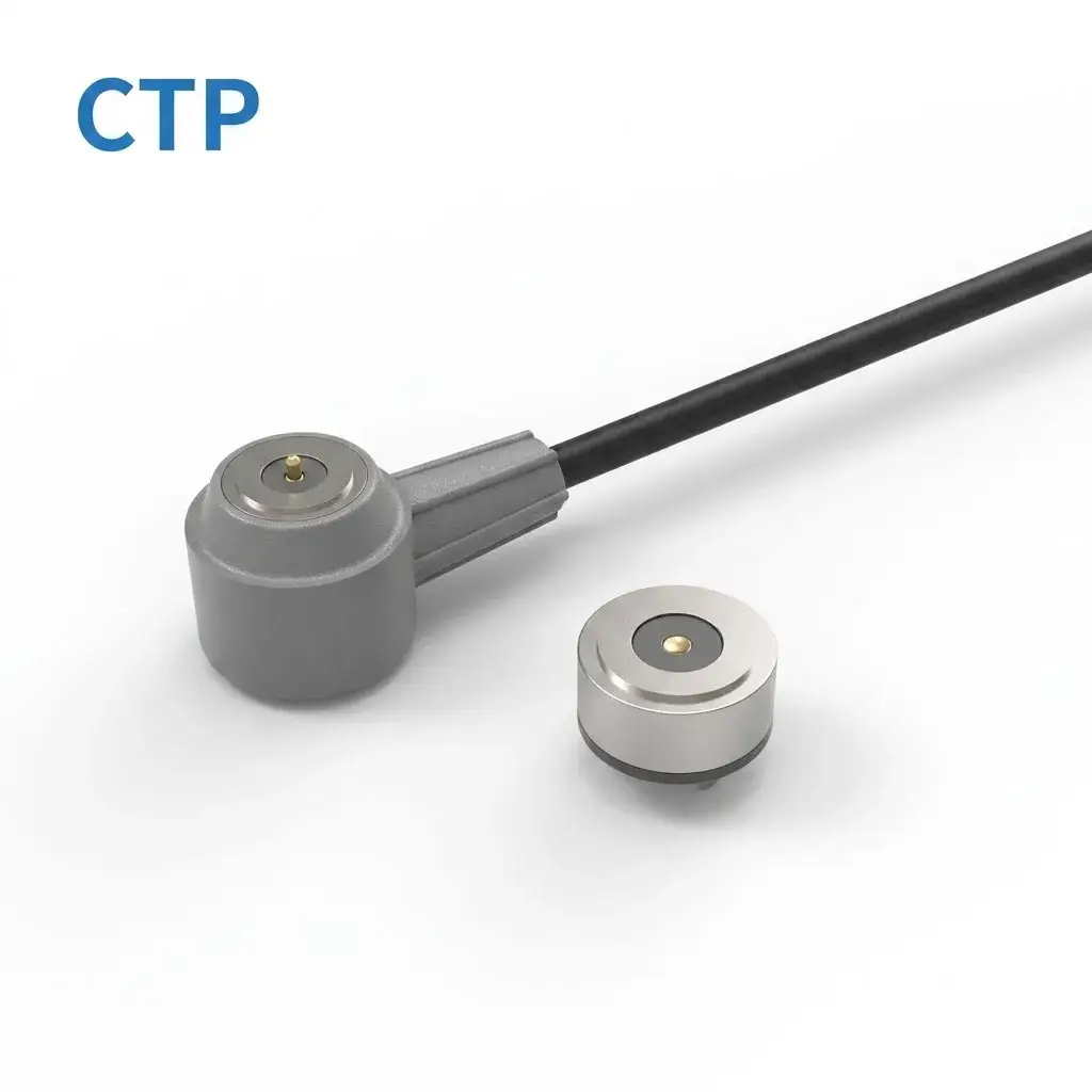
Where there is little space behind the terminal, the direction in which the cable leaves the head becomes especially useful. Our round side-exit data cable, CTP-MCC-RD-A09, combines a concentric mating interface with a cable leaving from the side and a separate round mating component.
The round side exit changes the packaging, not the circuit requirements
A service terminal on a shallow counter may benefit from a lead that travels sideways toward a protected route. The cable no longer needs to project straight behind the device before turning. The surrounding enclosure must still support the intended mating action and leave the lead free from sharp edges.
This cable’s signal path and remote termination are defined for the project. Its round appearance is not evidence that it rotates freely while operating or supports an unspecified data rate. The practical benefit is a side-exit geometry that can be developed with the product’s available space.
Choose the source end while the charging dock is still taking shape
A USB-C-ended two-contact assembly simplifies one supply route
Our two-contact magnetic cable with USB-C, CTP-MCC-2P-USBC-01, brings a compact magnetic interface and a USB-C termination into one assembly. It is a useful route to review for a device whose two-contact circuit and intended source are already defined.
The USB-C plug should be considered with the rest of the wiring. It does not, by its shape alone, promise USB Power Delivery, a particular charging current or a data connection through the two magnetic contacts. Confirm the source behaviour and the device-side requirements as one system.
For an OEM supplying docks with its own terminals, defining that complete lead can also make accessory ordering clearer. The approved head, cable length and source-end termination belong to one supplied assembly. The user receives a recognisable cable rather than several parts that still need to be matched.
A right-angle board interface can keep the cable outside the dock
Sometimes the cleaner arrangement is to move the connection onto the board at the desired mating direction. The CTP four-contact right-angle magnetic connector, CTP-MPC-4P-RA-TH-01, uses bent PCB terminals and a compact housing for side-entry integration.
That can suit a cradle whose board sits below or behind the docking face. It gives the designer a way to relate the contact interface to the board without requiring a straight connector to point through the wrong surface. The housing and the terminal’s support features should establish the seated position.
Consider a second version of the same dock mounted beside a workbench. Its incoming lead may approach from another direction even though the terminal is unchanged. Reviewing the cable exit, board interface and mounting arrangement together can preserve the familiar docking action while allowing a different cable route.
Measure the required lead along that installed route, including the distance through any cable channel and the accessible space around the supply plug. A straight-line measurement between the dock and its source can miss both. For the USB-C-ended assembly, check that the source plug remains reachable after the dock is mounted. For the side-exit head, check that the first supported section of cable follows the intended direction rather than being forced back across the head. These details help us define a finished assembly that fits your dock, instead of leaving the installer to solve its cable path.
As an OEM and ODM supplier, CTP can develop the magnetic interface and finished cable around the agreed arrangement. Our cable-exit orientation guide provides another way to compare the physical routes. Bring a view of the dock with the terminal seated and another with the device being removed. Those two views often make the best routing choice much easier to see.