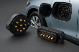
A shared charging station should make several devices easier to manage, rather than leave you with several separate cable problems. For an OEM building a dock for handheld accessories, small instruments or detachable modules, the useful starting point is the connection at each bay. Decide which devices need power only, which need additional functions, and how people will place and remove them.
Our multi-device charging dock connectors include branched magnetic cable arrangements and compact board-mounted contact assemblies. At CTP, we can develop the contact layout, mating parts and cable route around the dock you want to build. A four-head lead and a five-contact PCB assembly solve different parts of that job; neither needs to dictate the shape of the whole station.
Multi-device dock connectors should follow the bays, not crowd them
Picture a counter with a small reader, a removable sensor and two accessories returning to charge throughout the day. Their charging faces may sit at different heights. Their leads may also need different amounts of reach. Giving every bay an identical loose cable can make the station awkward to use, even when each individual cable works.
A branched assembly brings those routes into a more deliberate arrangement. The trunk can approach from the rear while the branches reach their own positions. The dock’s electronics still need to define supply capacity and charging control. More magnetic heads do not create independent chargers or an automatic power-sharing system.
Four square two-contact heads give four devices their own lead
Our four-head square magnetic cable, CTP-MCC-2P-SQ-MH-A11, has four separate square heads, each with two contacts inside a recessed mating area. It is a useful format to explore when several similar accessories need their own detachable connection without four completely independent cable runs.
The benefit is the physical organization of the leads. Branch length, trunk construction and each device-side mate can be developed with the spacing of the bays in mind. The electrical drawing must also identify every branch and its assigned load, so a tidy exterior is supported by a clearly defined power path.
With branches serving different devices, identify each bay on the drawing rather than relying on cable colour alone. That connects each physical lead to its intended device position during assembly and service, without assuming that every two-contact head is interchangeable.
A mixed-output cable can suit a station with different accessories
Some stations have a less uniform job. Our two-contact round multi-output assembly, CTP-MCC-2P-RND-MO-USBA-01, combines a USB-A input, two round magnetic branches and an additional plug termination. That gives a project team a different starting structure when the accessories do not all use the same physical connection.
The output functions come from the agreed wiring, rather than the number of visible plugs. Power, return and any supported signal function need to be assigned for the actual device. We can review that complete assembly with the branch routes, instead of treating the magnetic head and the rest of the cable as unrelated purchases.

Board-mounted charging contacts can keep the dock surface clear
A cable head is not the only route. For a device that settles into a shaped pocket, the dock may already provide alignment and support. A compact spring-contact block can then make the electrical connection at the bottom or side of that pocket. This can leave the user with a simple place-and-lift action.
A two-contact through-hole block keeps a simple bay compact
The CTP two-contact through-hole connector, catalogue reference CTP-P3559, holds a single row of two spring contacts in one housing. Its straight PCB tails suit a through-hole board layout. The dock structure locates the device while the spring-loaded contacts provide movement along their contact axis.
This format is worth considering for a bay with a clearly defined two-contact circuit. It is less suitable when the same interface needs additional identification or control paths. Those requirements should be settled before the housing opening and board footprint are fixed.
A five-contact assembly leaves room for separately assigned functions
Our five-contact connector assembly, CTP-PPC-5P-01, brings five spring-loaded contacts into a controlled housing. It contains no magnets. That is helpful where the dock’s own guides and enclosure already provide retention, and the electrical connection needs more assigned paths than a simple two-contact block.
For example, a family of handheld accessories might share the same docking pocket while using a defined identification contact to distinguish approved devices. Whether that circuit is appropriate belongs to the product design. The connector gives the designer contact positions to allocate; it does not add the identification electronics itself.
One manufacturer can coordinate the dock-side and cable-side choices
CTP, the brand of Shenzhen Yongtan Electronics, supplies magnetic connectors, finished magnetic cable assemblies and spring-contact components for OEM and ODM projects. That range is useful when a dock combines more than one connection style. We can review the bay interfaces and the cable build within the same product discussion, with each supplied part identified in the drawing.
Before a sample build, show the device positions, seating direction and available space beneath the dock. Add the contact functions and intended branch loads. For a finished cable, include the required ends and reach. For a board-mounted block, include the mating targets and installed contact position.
Our cable-exit orientation guide offers a closer look at how the lead can leave each connection without crowding the next bay.
If the station is expected to grow, leave the next bay in the layout conversation now. Our custom-project support route can help organize those requirements. The most useful charging station is the one whose connections feel obvious to the person returning a device, while remaining clear to the team assembling it.