
Sometimes the PCB is the part of the project you want to keep. The electronics work, the board fits and the assembly team already knows the connection. In other projects, the board is completely new and you have room to build the magnetic interface into its layout from the start.
Our magnetic cable PCB termination options give you different routes for those situations. CTP offers finished cables with PCB-mount mating connectors, wire-ended assemblies that can reach an existing connection, and multi-contact structures with matching contact plates. You can choose the format that works with the board and the product you are developing.
The benefit is flexibility at a very practical point in the design. The magnetic connection can be convenient for the person using the device, while its internal termination suits the electronics and the way the product is assembled.
A matching PCB connector gives the cable and board a shared starting point
Our four-contact USB-C magnetic cable with a PCB-mount mate brings the source plug, lead, magnetic head and receiving connector into one product arrangement. It is useful when a new board can be developed around a dedicated magnetic interface.
The device team can look at the mating connector while choosing its position in the housing. The board layout, available mounting space and magnetic connection area can therefore be considered together. That is a clearer starting point than selecting a cable head and leaving the device-side mating structure undefined.
A four-contact PCB mate can keep a small accessory’s connection focused
The four contacts provide separate paths for the functions assigned by the project. For a compact accessory, that may be an appropriate balance between the required electrical connections and the space available at the mating face. The source-side USB-C plug also keeps that end of the cable familiar.
Consider a small desk device whose board sits just behind one edge of the enclosure. A corresponding PCB-mount mate gives the team a defined part to place near that edge. The magnetic head can then approach the outside face while the internal connection relates directly to the board.
Our customization options include the cable construction, magnetic housing, strain relief and device-side connector structure. Those options give the assembly concept room to fit the product, rather than expecting the board and enclosure to accept a fixed generic arrangement.
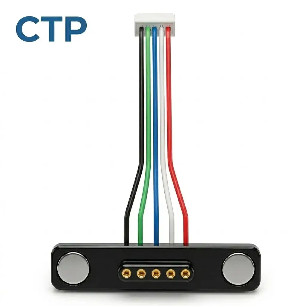
Five separate wire leads can work with a board that is already established
If your existing electronics already have a suitable connection, our five-contact magnetic cable with individual leads offers another route. The five wires can reach a PCB, module or harness through project-specific end processing.
This is particularly useful when the external appearance of the product is changing but the internal electronics remain valuable. A new magnetic face can become part of the enclosure while the cable leads connect to the board in a way that respects its existing layout.
Individual leads make the termination position less restrictive
The board-side connection does not have to sit immediately behind the magnetic face. The cable can reach it along a suitable internal route, with lead length, insulation and termination selected for that path. That can give the mechanical designer more freedom to place the outside connection where it feels convenient.
For a handheld instrument, for example, the magnetic face may work well near the base while the board connector sits closer to the display. Individual leads provide a way to link those positions without treating them as one rigid part. The electronics can retain their useful placement, and the external connection can suit the person holding the device.
The wire-ended format also allows the assembly approach to remain part of the decision. Prepared wire ends, a terminal connection or another suitable end structure can be discussed for the project. The value is having a cable format that leaves those choices open.
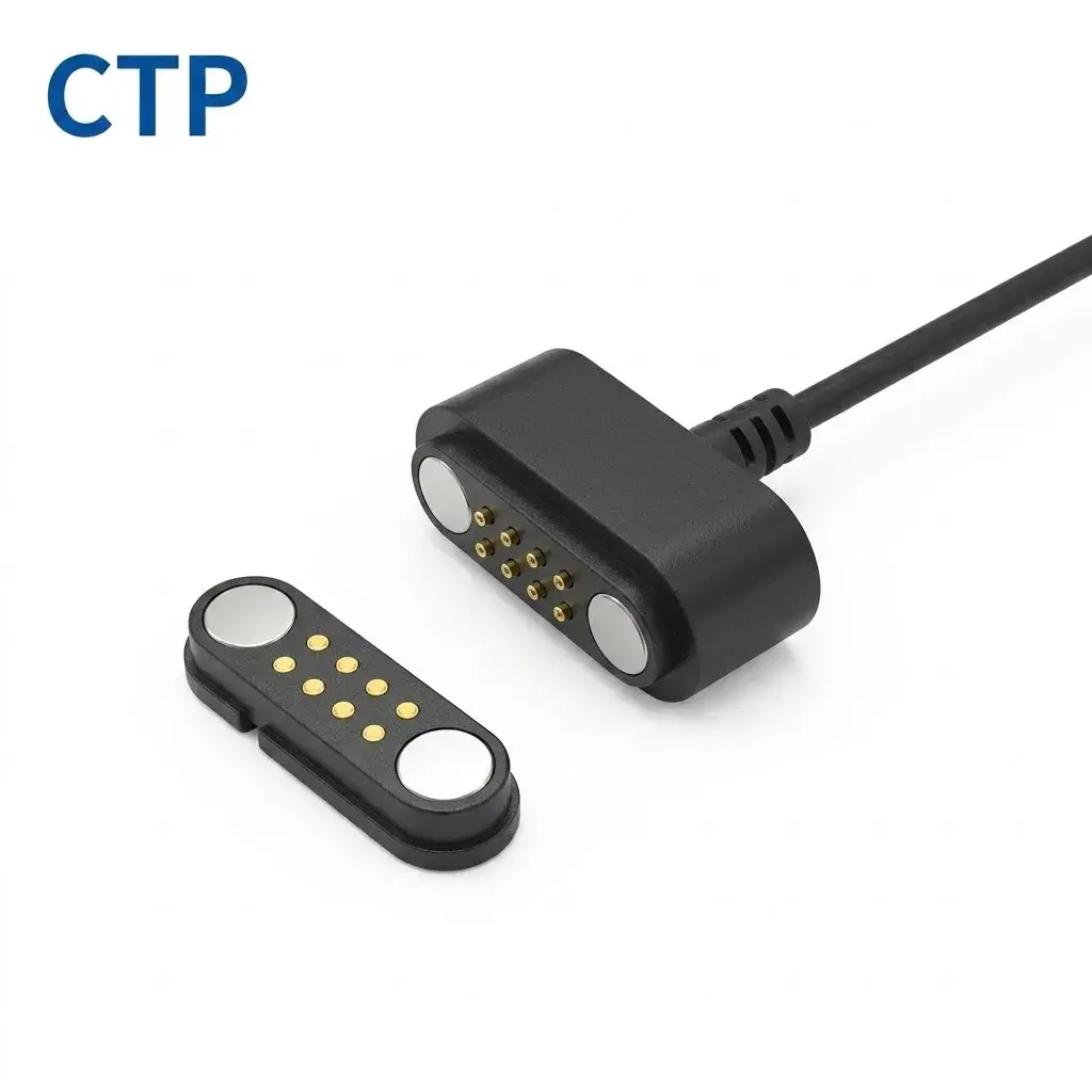
A dual-row contact plate offers a compact route for more electrical paths
The eight-contact cable with a matching 2×4 contact plate offers a different device-side structure. The cable head has two rows of four electrical contacts, and the corresponding plate provides the mating arrangement to consider within the product.
Eight contacts in two rows can suit a defined rectangular connection area
When a device needs several assigned functions, the two-row arrangement provides additional positions without requiring them all to sit in a single line. That gives the mechanical and board teams another shape to compare against the available area.
A compact control device may have a rectangular space reserved for its external interface. The 2×4 layout can be considered for that proportion, alongside contact spacing, mounting dimensions and the required electrical assignments. The matching plate makes the other side of the connection part of the same discussion.
The plate’s actual mounting and electrical connection to the PCB are developed for the project. We do not assume a solder process or board footprint from the photograph. Its visible benefit is the coordinated mating geometry and the number of electrical paths available for the design.
Two branches can connect electronics mounted in different parts of the device
Our six-contact assembly with dual-branch leads is useful when one magnetic interface serves more than one internal destination. Its main lead divides into two branches, whose lengths and terminations can reflect the product’s board positions.
Picture a device with a controller board in the main housing and a sensing module mounted closer to the enclosure edge. A branched arrangement gives those destinations separate physical routes. Each can have an end structure suited to its connection, while the outside of the device still presents one magnetic face.
This can help the internal cable look more intentional. The branch intended for the nearby board does not need to carry the same spare reach as the branch serving the more distant module. The chosen lengths can reflect the space and assembly access around each destination.
For a product team, that is a practical extension of PCB termination choice. You are deciding not only how a wire meets a board, but also how the cable reaches each board in the first place. The branch structure lets those decisions relate to the actual device layout.
Magnetic cable PCB termination can preserve useful design freedom
A custom magnetic connection should help the product team work with the device, rather than make every part of the enclosure and electronics revolve around one fixed cable end. Different termination formats create different kinds of freedom.
The PCB-mount mating connector is useful when the board can be developed alongside the interface. Individual leads suit a connection placed farther inside the housing. A contact plate offers a defined mating layout to integrate, while branches can reach separated modules.
This gives a buyer more than a selection of connector shapes. It gives the engineering team a choice of how much of the connection arrives as a coordinated cable arrangement and how much is integrated within the device. That distinction can make the product discussion much clearer.
| Your board situation | A useful CTP starting option |
|---|---|
| A new compact board with a dedicated magnetic interface area | A USB-C magnetic cable and matching PCB-mount mate |
| An established board whose connection is staying in place | A five-lead magnetic assembly with project-specific end processing |
| A device needing more separate electrical paths at one face | An eight-contact 2×4 assembly with matching contact plate |
| Two boards or modules mounted apart from one another | A six-contact cable with two branch terminations |
A tidy board connection leaves the housing more room to do its job
The available space inside a small product is shared by many things: the PCB, supports, display, battery or other electronics. A cable that reaches its connection along a sensible route can make that space easier to organize.
With individual leads, the team can consider where the wires pass and where their termination sits. With a PCB-mount mate, it can look at the relationship between the board edge and the outside magnetic face. With a branched assembly, it can give two destinations their own routes.
The cable also needs support near the board connection. The housing and cable arrangement can provide a more appropriate path for handling loads than leaving the termination to absorb movement from a freely pulled lead. That general design principle is useful whichever electrical connection method is chosen.
Our PCB mounting guide explores the receiving interface in more detail. For an initial product choice, the important point is simpler: the cable route and board connection can be developed together instead of competing for whatever space remains.
The termination format can suit the way the enclosure is assembled
The board connection is also part of the product’s physical assembly. Some boards slide into a housing from one end. Others are fixed to a cover before that cover is brought toward the rest of the device. A useful cable format gives the team a realistic arrangement to work with in that position.
Individual leads can be helpful when the magnetic face is fitted to one section and the PCB is installed separately. Their length gives the two parts a defined connection while the housing is still open. The opposite-end processing can suit the board connection, so the team is working with a deliberate assembly rather than an unplanned bundle of wire.
A PCB-mount mating connector may suit a more direct layout. The board and receiving interface can be positioned together, with the magnetic face related to the enclosure opening. For a new compact product, that can make the connection area easier to visualize while the board and housing are still being developed.
Two branch terminations offer another useful arrangement when a cover-mounted module and a main board sit in different sections. The branches can have their own lengths and end structures. That gives the device team separate routes to consider as the housing is assembled, with one magnetic interface on the outside.
The advantage of this choice is practical. You can begin with a cable format that resembles the way your device goes together, then develop its dimensions and connections for the actual build. Our range provides several such starting points, with different balances between a direct board mate and the freedom of separate wire leads.
That helps the cable developer and electronics team discuss the same product. The board-side termination, lead route and outside magnetic connection all have a place in the arrangement, so the final accessory can feel more coordinated from the inside out.
The best board-side choice also supports everyday connection at the outside face
The user interacts with the magnetic head, while the PCB sits out of sight. The two should still support the same design intention. A convenient outside position needs an internal connection that fits the board and mounting arrangement behind it.
For the handheld instrument, separate leads may let the magnetic face sit where the user’s hand can approach comfortably. For the new desk accessory, a coordinated PCB mate may give the board and external interface a more direct relationship. Different product layouts lead naturally to different termination choices.
CTP’s magnetic cable formats give you several ways to explore that relationship. The useful option is the one that fits the electronics you are building and the connection you want the user to experience. When those two ends are considered together, the cable becomes a more convincing part of the finished product.
