A cable with branches in the right places can make a device much easier to put together. The magnetic connection sits where the user needs it, the leads reach the electronics they serve, and the whole arrangement has a clear shape. That’s the appeal of a magnetic connector cable harness developed around the product.
CTP offers magnetic assemblies with individual wire leads, dual-branch terminations, multiple contact layouts and two-head power connections. We can review the main cable, branch lengths, conductor choices and terminations together, so the wiring arrangement has a reason to look the way it does.
For an OEM equipment maker, this gives the cable a more useful role than simply joining two points. It can connect separate modules, bring several electrical functions to one magnetic face and help the inside of the device feel as deliberately arranged as the outside.
Our six-contact magnetic harness gives two destinations their own route
The six-contact magnetic cable with dual-branch leads, CTP-MCC-6P-WH-DATA-01, combines a magnetic interface, main cable and two branch terminations. It is a useful starting format when the electrical connections need to reach different places within a device.
A controller board may sit near the display, while a sensing module belongs closer to the part being measured. Those positions make sense for the device’s function. A cable that divides into two appropriate branches can support that layout, allowing the electronics to stay where they are useful.
Two branch lengths can suit two different board positions
The branches do not have to be treated as identical extensions. Their lengths, conductor specifications and terminal structures can be developed for the destinations they serve. That makes the physical arrangement more specific to your product.
For the controller and sensor example, the branch reaching the lower module may need a longer route through the housing. The other may connect close to the magnetic entry point. Giving each branch a sensible reach can reduce the amount of spare wire that has to be folded into the remaining space.
The six contact paths are allocated according to the device’s circuit. They may serve power, reference, signals, detection or other agreed functions. The advantage of this structure is the combination of contact-allocation choice and a branched physical format, both developed around the same device.
A magnetic connector cable harness can bring several functions to one face
A product may need more than power at its detachable connection. A sensor-based device could also need control, identification or signal paths. Bringing those defined functions through one magnetic interface can help keep the outside of the product focused on a single connection area.
That can be particularly useful on a compact instrument. The user sees a clear place to attach the cable, while the harness behind the face directs the assigned connections to the relevant electronics. The housing does not have to display a separate connection for every internal destination.
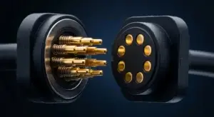
Our range offers different contact counts for this reason. The six-contact branched assembly is one option. Where the circuit needs more electrical positions, an eight-contact arrangement offers a different starting layout. The choice follows the functions the product actually needs.
A single outside face can also make the accessory relationship easier to understand. The cable is visibly associated with the device’s dedicated interface. Its internal mapping then supports the functions that make that connection useful, without asking the person using it to understand the branch wiring behind the enclosure.
Two round magnetic outputs are useful for a two-module lighting product
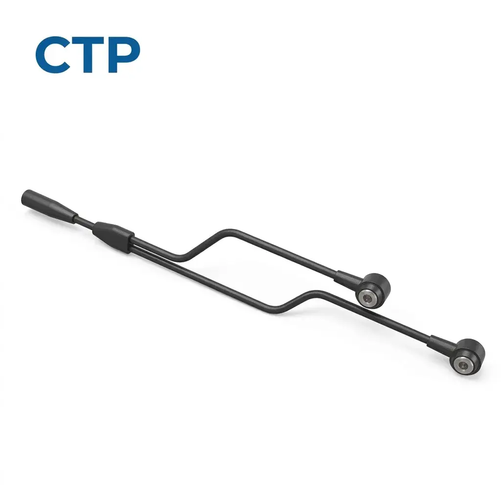
Our dual-head magnetic power cable for LED applications, CTP-MCC-2P-RD-A15, approaches branching from another direction. A common cable section divides into two leads, each ending in a round two-contact magnetic head.
Two lighting modules can share a deliberately arranged cable assembly
Imagine an illuminated display with two removable light sections. Each section needs a power connection, and each occupies a different position within the display. The dual-head format gives the design team a recognizable harness concept for that arrangement.
The main section and branch lengths can be developed around those positions. One branch may follow the near edge of the display; the other may travel farther across the structure. The useful feature is that the two output routes belong to one cable design.
The electrical design determines each branch load and the combined current in the shared section. That is developed for the application, including whether both outputs operate together. The product structure provides two detachable magnetic power interfaces; it does not rely on an assumed rating taken from a product name.
For the person handling the display, the two round heads can offer a consistent connection approach at the lighting modules. For the equipment maker, the branches provide a way to arrange the cable around the product rather than adding separate leads wherever space happens to remain.
Individual leads suit electronics that already have a connection method
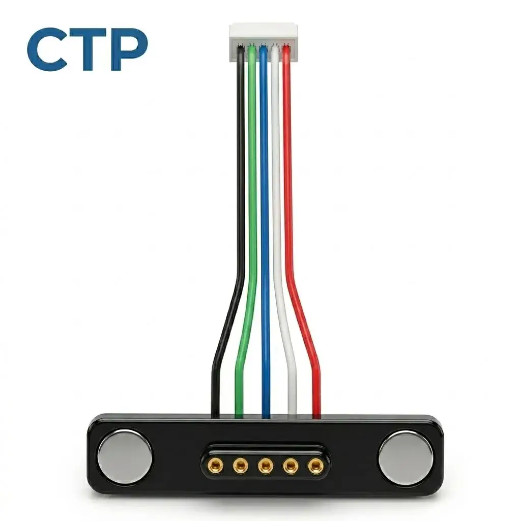
The five-contact magnetic cable with separate leads, CTP-MCC-5P-LIN-WL-01, is useful when the device needs freedom at its internal end. Its five conductors can connect to a board, module or harness through project-specific wire processing.
Five wire leads can preserve a board-side arrangement you want to keep
A device maker may already have a suitable internal connector on a well-established PCB. The product’s enclosure or external cable interface may be changing while that board remains useful. Separate leads allow the new magnetic face to connect into the existing arrangement.
The practical benefit is flexibility in where the connections end. Wire length, color, insulation and termination can reflect the assembly route. The magnetic housing can be positioned for the outside user while the leads reach the internal electronics in an appropriate way.
This format is also easy to relate to a larger harness. The device team can identify which connections need to remain as individual leads and which require a terminal or connector at their destination. The supply scope can be developed around those choices.
Eight contacts in a 2×4 layout give a different option for a busy interface
Our eight-contact dual-row magnetic cable, CTP-MCC-8P-DR-PAIR-DATA-01, has two rows of four contacts and a matching contact plate. It provides additional electrical positions in a mating-face shape that can suit a different enclosure proportion from a longer single row.
For a device bringing several assigned functions through one face, the extra positions can give the circuit designer more allocation freedom. Power, references, detection and signals can be arranged according to the actual schematic. The cable and its mating plate can then be reviewed with the board and mounting structure.
The value is the choice of layout, not the contact count on its own. A simpler product may work comfortably with four or five contacts. A more involved interface may need the eight positions. Having both kinds of structure available helps the product team choose a connection that reflects the device’s functions and shape.
The matching plate is useful because it makes the device side of the interface visible during development. The cable head and receiving structure can be considered as a pair, rather than leaving the internal team to develop around an unspecified mating part.
A harness can make the inside of the product look more organized
Internal appearance matters to the people building and maintaining the device. A branch that follows a clear path is easier to understand than a long, loosely arranged bundle. Different terminal requirements are also easier to discuss when the cable’s intended destinations are clear.
Our main and branch length options provide something practical to adjust. If a module sits farther away, its branch can be considered for that reach. If two boards use different connection structures, the branch end processing can reflect their needs.
This is useful when the housing is assembled from more than one section. The leads need to move through the available space while those sections come together. A device-shaped harness gives the team a definite arrangement to evaluate during assembly, instead of leaving the cable route to vary from one build to another.
The same clarity can help explain the product to a purchasing team. A six-contact magnetic head with two specified branch ends is a concrete assembly. The discussion can focus on that structure’s lengths, destinations and electrical functions rather than on several independent connector purchases.
The main cable and branches can have different practical priorities
The part of a cable outside the device may be handled regularly. An internal branch may remain in place once the enclosure is assembled. Another section may need enough free length for the housing to open. These different roles are a good reason to develop the harness as a complete arrangement.
On the six-contact design, for example, the main lead, two branch lengths and end structures can all be reviewed against their jobs. The objective is a cable route that uses the space sensibly and reaches the right connections. The electrical design still establishes how the six positions are allocated.
On the dual-head LED cable, the shared section and output branches have different load conditions as well as different positions. Looking at them within one harness brings the physical routes and the intended operating condition into the same discussion.
That is a useful advantage of custom development: the cable does not have to be treated as one undifferentiated length of wire. Its distinct sections can be developed for the places they occupy and the functions they serve.
Branch lengths matter when the housing opens as well as when it closes
A small instrument may look like one solid enclosure once it is assembled, even though its display, controller and sensor are mounted in different sections. During assembly, those sections need to be brought together with the cable already connected. The branch arrangement can make that operation easier to understand.
For a six-contact harness, one branch might reach a board fixed in the rear housing while the other serves a module attached nearer the front. Their useful lengths depend on those positions and the space needed while the housing is open. Developing the branches around that arrangement gives the team a cable concept suited to the real build.
Terminal choices also help define the connection. A branch intended for a board connector can be developed with the appropriate end structure, while another branch can suit a different module connection. The harness then reflects the device’s separate destinations without requiring the electronics to use identical terminations everywhere.
That is a practical benefit of the dual-branch format. It gives the product maker two deliberate routes to work with, rather than a single long bundle whose final shape remains undecided. The magnetic head still presents one outside interface, while the internal cable can follow the device’s actual construction.
A more useful harness begins with the shape of your device
A product with separated boards, two lighting modules or several functions at one detachable face gives the cable a particular job. CTP’s wire-ended, branched and multi-contact formats provide different starting structures for that job.
You can compare them in our magnetic cable assembly range. The custom cable development overview also explains how a project moves from the required functions into an assembly concept.
A well-chosen magnetic connector cable harness can make the outside connection simple while keeping the internal routes purposeful. When the head, main lead and branches are developed around the same product, the wiring has a better chance of feeling like part of the design from the beginning.