A charging lead should fit comfortably into the way a device is used. It should reach the right place, sit neatly beside the product and connect to a source the user recognizes. Inside that simple arrangement, the conductors and contact interfaces need to suit the power the device actually requires.
Our custom magnetic cables give product developers several ways to bring those needs together. Cable length, wire gauge, the magnetic head and the opposite-end connection can be selected as parts of one assembly. That is particularly useful when you are looking at magnetic charging cable voltage drop: you can consider the whole route to the device, rather than choosing a connector first and accepting whatever lead happens to be attached.
CTP offers finished USB-C and USB-A magnetic cable formats, wire-ended assemblies for custom integration and branched structures for more than one destination. Each provides a different starting point for a connection that fits the product.
A charging cable can be designed around the distance it really needs to cover
One of the simplest advantages of a custom cable is getting the length right. A handheld device used beside its charging station may need a very different lead from an accessory mounted across a display. Giving both the same cable length can leave one with unnecessary coils and the other with an awkwardly stretched connection.
With a custom assembly, the route can reflect the actual installation. A shorter practical route also reduces conductor resistance when the wire construction remains the same. That does not make length the only electrical decision, but it gives the design team a useful way to address both appearance and power delivery together.
Imagine a small handheld instrument resting in a desk dock. The cable needs enough reach to connect easily, but a long loop behind the dock may add little value. Choosing a suitable length can leave the work surface neater and make the connection feel like part of the instrument’s design.
For the user, that is a visible benefit. For the electrical designer, it creates a known route that can be considered alongside the conductors, source and load. Both sides of the product are working from the same cable choice.
Magnetic charging cable voltage drop is a complete-path question
Voltage drop is the difference between the voltage supplied and the voltage available at the device while current is flowing. Wire resistance, terminations and contact interfaces all contribute. The return path is part of the circuit too, so the useful view is the complete connection from source to load and back.
Our custom approach allows cable length and conductor size to be considered with the magnetic interface. It gives you room to work toward the device’s voltage requirement without treating the cable as a fixed accessory selected at the end of development.
A thicker conductor can reduce wire resistance, but it also affects the lead’s diameter and feel. A shorter cable may reduce loss, but it still has to reach comfortably. Those are normal product decisions. The benefit of developing the assembly together is being able to balance them around the way the device will actually be handled.
Texas Instruments discusses voltage loss in power connections as a system concern. The same general principle applies when choosing a custom magnetic cable: the connector, lead and receiving connection share the job. No single photograph or contact count can describe the performance of all three.
Our USB-C option joins a familiar plug to a custom magnetic interface
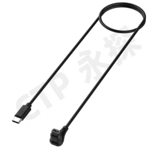
The CTP four-contact USB-C magnetic cable, CTP-MCC-4P-USBC-DATA-01, includes a USB-C plug, cable, magnetic head and matching PCB-mount connector. It suits projects that want a recognizable source connection and a magnetic interface developed for the device itself.
A matching board connector helps the charging route feel complete
Having the mating part represented is useful while the board and housing are being arranged. The cable meets a defined device-side interface, and the board team has a corresponding connection to consider. Its position can be reviewed together with the cable outlet and the available internal space.
For a compact desk accessory, that can support a tidy charging arrangement. The cable’s magnetic head can meet the product where it is comfortable to connect, while the receiving connector relates directly to the electronics. Cable length, conductor choice and strain relief can then be developed for that installation.
The supported electrical functions still come from the agreed circuit and USB-C wiring. The plug shape is not a blanket promise of a charging protocol. The useful advantage is the coordinated assembly format, with room to define the particular functions your device needs.
USB-A remains a practical choice for equipment already in use
Our USB-A magnetic cable with a linear four-contact head, CTP-MCC-4P-USBA-DATA-01, is a practical option for devices used with an established USB-A station. It keeps a familiar plug at the source and a dedicated magnetic connection at the device.
A product used with an existing USB-A station may benefit from keeping that familiar connection. You can develop the magnetic end for the new device without assuming that every workstation or accessory needs a different source-side socket.
Four assigned contacts can serve a compact charging accessory
The four contact paths can be allocated around the project’s required power, reference and other supported functions. The cable construction can also reflect the operating current and the distance from the source. This gives the assembly a defined purpose instead of relying on a universal contact arrangement.
The result can be a clearer accessory offering: a cable intended for the product, with a recognizable source plug and a custom magnetic connection at the other end. That is useful both for the person choosing the cable and for the team explaining how the device connects.
Individual wire leads make room for a power board inside the product
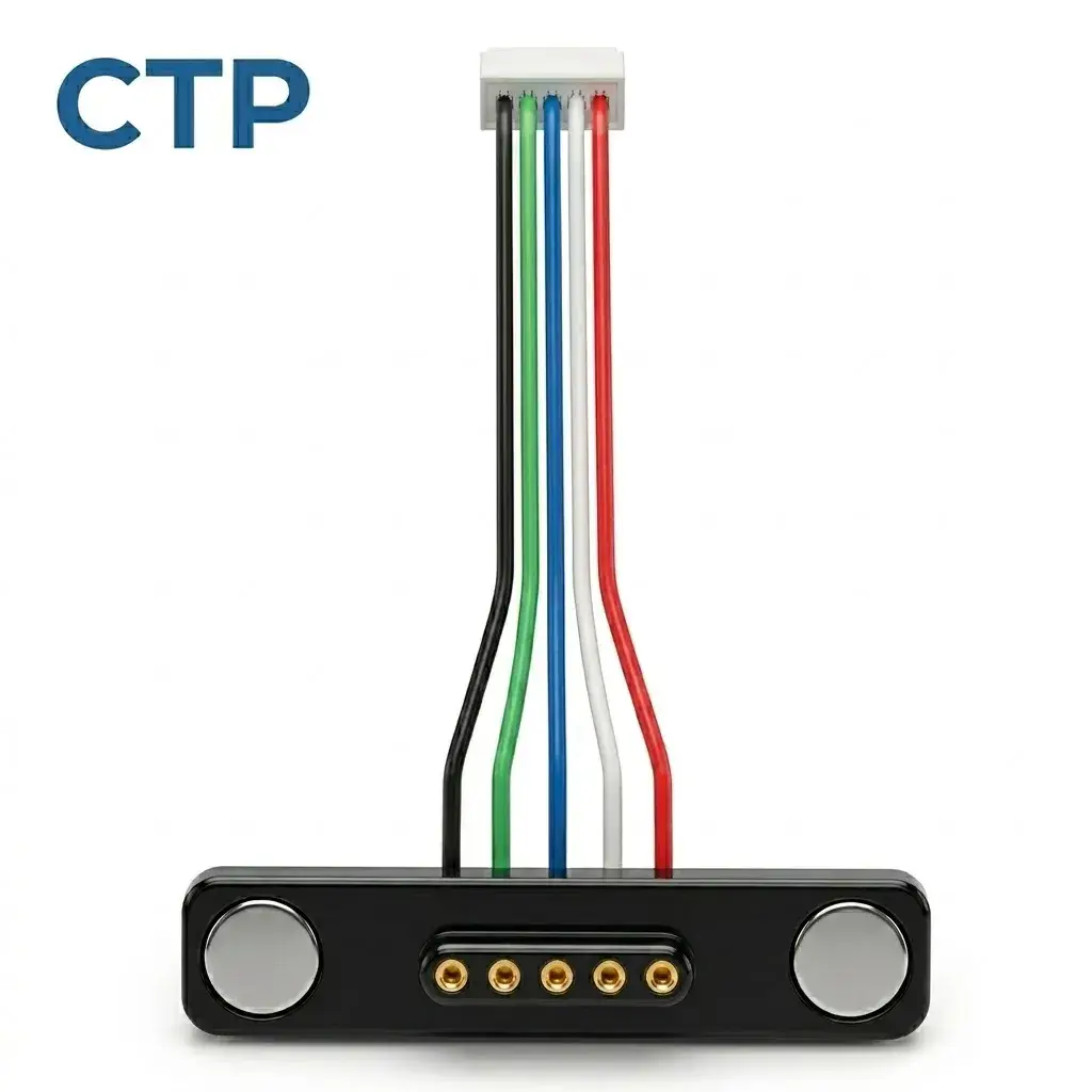
Some devices have their own power input arrangement within a larger enclosure. Our five-contact wire-ended cable, CTP-MCC-5P-LIN-WL-01, provides separate leads that can connect to a PCB, module or harness through project-specific processing.
This is useful when a magnetic face belongs on the outside of the housing while the receiving power board sits further inside. The leads can be developed for that internal route, and their end treatment can suit the preferred board connection. You are not limited to a fixed USB plug where the design needs prepared wires or a terminal.
For an equipment maker, the advantage is control over how the outside cable joins the inside electronics. Wire length, gauge, insulation and termination can be considered together, including their contribution to the complete power path. The magnetic interface and the internal lead become parts of the same assembly choice.
Two magnetic LED outputs can make the wiring look more intentional
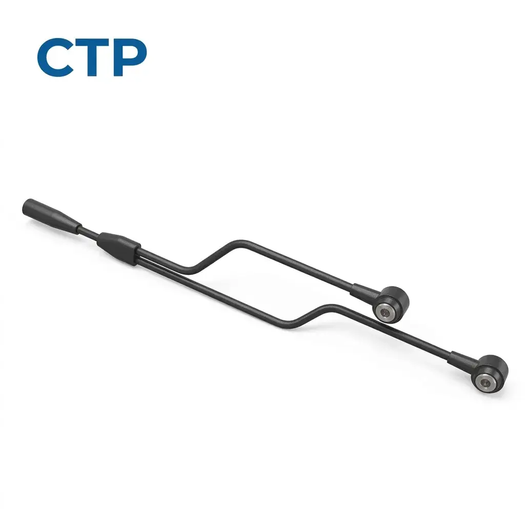
A product with two removable lighting modules needs a different cable structure from a single handheld charger. Our dual-head round magnetic power cable for LED applications, CTP-MCC-2P-RD-A15, has a common cable section that divides into two branches, each ending in a round two-contact magnetic head.
Two branches can reach two different lighting positions
Think of a display with two detachable illuminated sections. One lighting module may be close to the cable entry and the other farther away. Branch lengths can be selected around those locations, so each output has a route that makes sense within the product.
The benefit is a more coherent cable arrangement. The two outputs belong to one defined harness rather than appearing as unrelated cables added to the display. The round magnetic heads also give each lighting section a detachable power interface.
Each branch still has its own load and resistance, and the common section has to suit the combined operating condition. Those details are defined for the project rather than assumed from the product’s older URL. In a custom development, the branch lengths, wire gauges and intended simultaneous operation can be reviewed together.
A charging connection can also serve the device’s other functions
A magnetic power connection may be part of a more capable accessory. The device might need to recognize when an accessory is attached, exchange a supported signal or carry a control function alongside power. Our four- and five-contact formats give the circuit designer several electrical paths to work with.
For a small desktop instrument, a dedicated detection connection can be useful within the product’s own circuit. The cable does not create that function by itself; it provides the assigned path between the two sides. This lets the device electronics determine what should happen when the cable is connected.
The five-lead assembly is particularly adaptable when those functions need to reach a custom internal board. Each lead can have a defined destination, so the magnetic connection reflects the instrument’s actual requirements. The four-contact USB versions offer a different balance when a familiar source plug is part of the intended arrangement.
This is one reason to choose the contact layout before settling the cable construction. Power and return conductors need to suit their loads, while the other conductors serve their assigned functions. The lead’s flexibility, diameter and length can then be developed around that combination rather than around a guess based on contact count.
For the product maker, the appeal is a purposeful connection: one magnetic interface designed for the functions the device uses. It can keep the enclosure’s connection area simple while giving the electronics team the paths it needs behind that area. The supported functions and power budget remain specific to the finished product.
A charging cable should be comfortable to handle
A cable that fits the power requirement also has to feel appropriate for the device. A very stiff lead beside a lightweight accessory may influence how the product rests on a desk. A generous cable loop may be useful for movement but awkward in a small carrying case. Cable construction brings these everyday details into the design.
We can review the jacket, housing, outlet direction and strain-relief structure alongside the conductors. The purpose is to develop a connection that suits both the circuit and the person using the product. A charging accessory should look and feel considered, even though much of the work behind it is hidden inside the cable.
This is especially useful for a handheld device that is connected and disconnected throughout the day. Its cable needs a suitable approach direction and enough free length for comfortable handling. The magnetic head, lead and device-side mounting can then be evaluated together in that normal position.
The same thinking helps a lighting assembly that is handled only occasionally. Its most useful feature may be an orderly installed route, with branches that reach their modules and can be separated when needed. Different uses deserve different cable choices.
A well-chosen cable makes the power connection easier to live with
The strongest reason to consider a custom magnetic cable is the ability to bring these choices together. You can select a source-end format, use a magnetic interface that suits the product, and develop the cable length and conductor arrangement around the actual load and installation.
Our magnetic cable assemblies cover several of those starting points. The cable construction guide also explains how the conductor, jacket and molded parts relate to the finished lead.
For your device, a useful conversation about magnetic charging cable voltage drop begins with the connection you want to build: where it starts, where it ends, how much power the device needs and how the cable will be used. From there, the electrical and physical choices can support a product that is tidy, convenient and properly defined for its job.