Designing a magnetic connector for an industrial handheld terminal starts with the full docking workflow—not pin count or magnet strength alone. Industrial handheld terminals are repeatedly removed from and returned to charging cradles, vehicle docks and fixed workstations. In warehouses, field service, production and transportation, the interface may be operated with gloves, exposed to dust or residue, and expected to support charging, communication or service access without slowing the operator.
A magnetic connector can be a useful interface architecture for these devices, but the design cannot begin with pin count or magnet strength alone. The project must define what the terminal needs to do when it approaches the dock, while it is seated, when it is partially mated and when it is removed. Those operating states determine the Pin Map, mechanical guidance, cable or dock electronics and validation plan.
Engineering summary: For an industrial handheld terminal, magnets should assist capture and retention, while the device housing and dock geometry control final alignment and pogo-pin compression. Charging and data must be defined as separate system functions. The connector, PCB, cable, dock and enclosure should then be validated as one assembled interface.
Start with the handheld workflow—not the connector shape
The same rugged terminal can experience several different connection scenarios during one shift. A desk cradle may prioritize one-handed insertion and charging. A vehicle dock may introduce vibration and cable movement. A service fixture may need controlled communication or programming. A wall-mounted station may require retention while still allowing fast removal.
Before selecting a connector, document the operating states:
- Approach: How much position and angle variation can the user introduce?
- Capture: Should the magnet pull the terminal toward the dock, or merely help it settle after the housing is aligned?
- Seated: What holds the final position and establishes the pogo-pin working stroke?
- Active: Is the dock charging only, carrying project-specific data, identifying an accessory or enabling service functions?
- Partial mating: What happens if only one side, one row or selected contacts touch first?
- Removal: Can the terminal be removed under electrical load, and in which direction?
- Empty state: Are exposed contacts energized when no terminal is present?
- Maintenance: How are residue, dust, metallic particles and cleaning fluids handled?
This workflow definition prevents a common mistake: choosing a magnetic connector that looks mechanically convenient but does not match the electrical sequence, docking tolerance or service environment.
1. Define the supply scope before selecting contacts
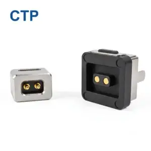
An OEM request for a ‘magnetic connector’ can describe several different deliverables. The project may need only a device-side connector component, a matched connector pair, a finished magnetic cable assembly, a complete dock harness or a dock subassembly that includes electronics. Each scope creates different drawing, termination, validation and production responsibilities.
For many handheld projects, the finished assembly is the commercially relevant unit. Connector geometry alone does not define cable length, conductor allocation, shielding, strain relief, opposite-end termination or how the dock connects to the host system.
2. Separate charging requirements from data requirements
A charging interface and a data interface may share the same connector body, but they are not the same engineering problem. The Pin Map should define the function and electrical state of every contact: power, return, detection, identification, control, signal reference or project-specific communication. Physical contact count does not prove a protocol, a data rate or a safe power architecture.
For the charging path, define at least:
- nominal, minimum and maximum voltage;
- continuous current, peak current and peak duration;
- power-enable, detection and reverse-polarity behavior;
- acceptable voltage drop and temperature rise in the assembled path;
- whether the terminal can be removed while energized;
- the charger, dock, cable, connector, PCB and battery-charging architecture.
Two simple relationships help explain why the complete path matters: voltage drop increases with path resistance (Vdrop = I × Rpath), and resistive power loss increases with the square of current (Ploss = I² × Rpath). These equations do not replace testing, but they show why contact resistance, wire size, termination, PCB copper and temperature should be reviewed together.
For project-specific data or communication, define:
- protocol and required functional mode;
- signal and return allocation;
- contact order and partial-mating states;
- PCB transition and routing;
- cable construction and shield continuity where required;
- channel-level validation criteria.
A multi-contact connector may support selected signals after the complete channel is designed and validated. It should not be described as USB, high-speed or data-capable based only on the number of pins. If the terminal needs both daily magnetic docking and standard USB service access, a dual-interface architecture may be more practical than forcing every function through one dock.
3. Magnetic capture is not final alignment
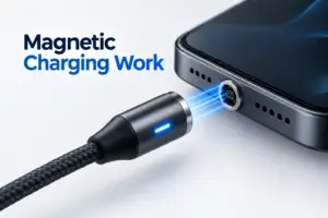
Magnets can assist the terminal as it approaches the dock and can provide seated retention. They should not be the only features controlling lateral position, rotation, final gap or pogo-pin compression. Those dimensions should be established by the connector housings, locating rails, bosses, pockets, mechanical stops and the device enclosure.
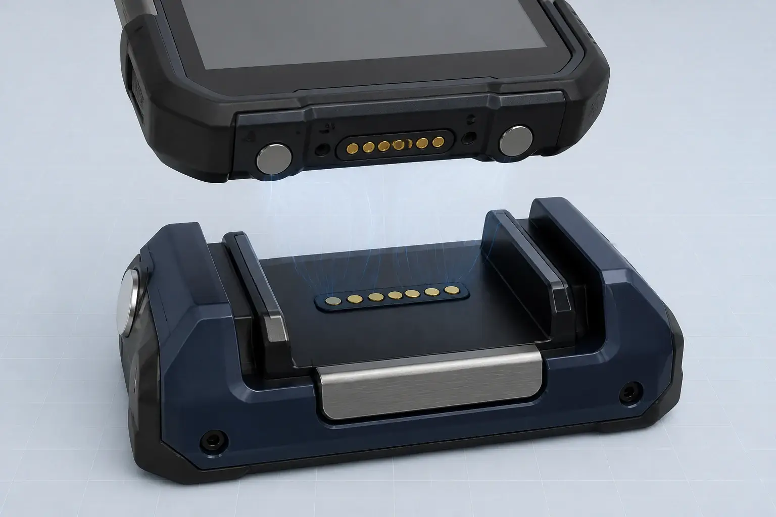
Magnetic capture should assist approach while the housing and mechanical stops control the final seated position.
This separation of functions is important because magnetic force acts over a distance, while electrical contact performance depends on a defined working position. A terminal can feel attached even when it is tilted, offset or only partly seated. The design should therefore evaluate the approach envelope and every credible partial-mating condition, not only the nominal CAD position.
Mechanical questions to resolve include:
- What are the minimum, nominal and maximum working-stroke conditions after tolerance stack-up?
- Can the user seat the terminal one side first or at an angle?
- Do the contacts carry structural load that should instead be supported by the enclosure?
- How do axial, lateral and peel removal directions change retention?
- Does the dock need an additional latch for vehicle vibration or mobile equipment?
- Can the interface be inspected and cleaned without damaging the contacts?
4. Design the dock and cable as part of the interface
The handheld terminal may connect to a desktop cradle, vehicle dock, wall station or magnetic cable. Each route changes the mechanical load path and the electrical architecture. A cable assembly introduces bending, pull and torsion near the connector. A fixed dock introduces fixture alignment, enclosure stiffness, PCB support and upstream cable routing.
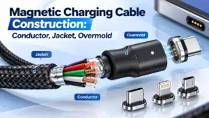
For a finished magnetic cable assembly, specify the opposite end—not only the magnetic end. Define whether the assembly terminates in USB-C, USB-A, a board connector, a wire harness or another project-specific interface. Confirm cable length, conductor count, wire size, shielding where required, jacket material, outlet direction, strain relief and any overmold or enclosure constraints.
For a dock, decide where power negotiation, voltage conversion, current limiting, terminal detection, data bridging and status indication are implemented. These functions may be in the upstream adapter, cable, dock electronics or terminal. They are not automatically provided by the magnetic contacts.
5. Review contamination, cleaning and service conditions
Industrial handheld interfaces may collect dust, fibres, hand oils, moisture, cleaning residue, wear debris and metallic particles attracted by magnets. The actual exposure depends on where the terminal is used and how the dock is maintained. A flush or shallow interface can simplify access for inspection, but it does not automatically make the connector waterproof, dustproof or maintenance-free.
If ingress protection is required, define the sealing boundary of the complete installed assembly. The connector, feedthrough, enclosure, gasket compression, fasteners, cable exit and manufacturing variation may all affect the result. The relevant rating should be attached only to the tested configuration and test conditions—not to a pogo pin in isolation.
The project review should document:
- expected dust, moisture, chemical and cleaning exposure;
- whether contacts are energized while exposed;
- foreign-object and adjacent-contact bridging scenarios;
- approved cleaning method and inspection access;
- replaceable parts and field-service procedure;
- environmental test scope for the assembled terminal and dock.
6. Build the validation plan from the failure modes
A useful validation plan connects each requirement to a method, test condition and acceptance criterion. There is no single universal cycle count, vibration profile or ingress test that proves suitability for every industrial handheld terminal. The test scope should follow the intended electrical load, mechanical use, environment and customer qualification plan.
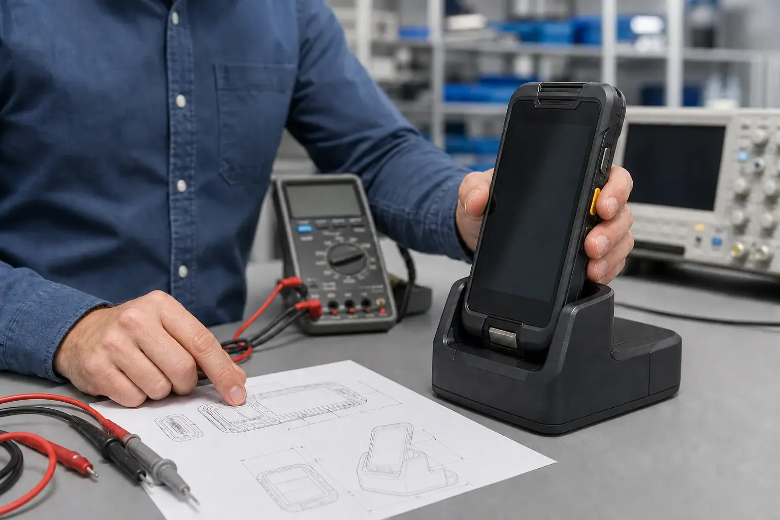
A connector proposal should be reviewed with the device, dock, drawing, electrical allocation and validation plan.
| Design question | Recommended evaluation | Example acceptance basis |
|---|---|---|
| Contact position | Measure working stroke, final gap, target flatness and tolerance stack | Approved drawing at minimum/nominal/maximum assembly conditions |
| Power path | Measure loop resistance, voltage drop and temperature rise at defined loads | Project electrical limits and stable condition |
| Partial mating | Test offset, tilted and one-side-first engagement | No unacceptable short, wrong function or uncontrolled power state |
| Data function | Validate the complete connector–PCB–cable channel | Required protocol and project-specific functional criteria |
| Docking use | Cycle at defined speed, stroke, electrical state and removal direction | Drawing, electrical and functional acceptance after test |
| Vibration/shock | Monitor continuity and inspect mechanical support under the defined profile | Customer equipment criteria and no unacceptable damage |
| Cable durability | Bending, pull, torsion and strain-relief tests where a cable is supplied | Approved cable drawing and assembly criteria |
| Environment | Representative dust, moisture, cleaning and contamination exposure | Specified assembled-product requirement |
OEM requirement checklist
Send the following information for an efficient engineering review:
- Application and handheld model concept: warehouse terminal, scanner, field-service device, industrial tablet or another device type.
- Supply scope: connector component, matched pair, finished cable assembly, dock harness or dock subassembly.
- Pin Map: power, return, signal, detection, identification, control and unused contacts.
- Electrical requirements: voltage range, continuous and peak current, power-enable logic and data function.
- Available installation space: device and dock length, width, height, PCB area and enclosure wall.
- Mating direction and user interaction: approach angle, glove use, one-handed docking and removal direction.
- Cable requirements: length, outlet direction, conductor, shield, jacket and opposite termination.
- Environment: dust, moisture, cleaning, vibration, temperature and contamination conditions.
- Validation scope: project-specific electrical, mechanical, environmental and lifecycle acceptance criteria.
- Available files: 2D/3D drawings, PCB information, existing connector details and estimated prototype/production quantity.
Frequently asked questions
How many pins does an industrial handheld terminal need?
There is no universal pin count. Start from the required power, return, detection, identification, control and signal functions. Some contacts may also be used in parallel for power or return, subject to the complete current-path design and validation.
Can one magnetic interface support charging and data?
It may support both when the Pin Map, contact layout, PCB routing, cable construction and complete channel meet the project requirements. Pin count or continuity alone does not establish a protocol or data rate.
Is a stronger magnet always better for a rugged dock?
No. Capture, seated retention and separation are different requirements. Excessive retention can make removal difficult or increase peel and cable loads, while magnetic force alone does not define final alignment or pogo-pin working stroke.
Does a flat contact surface make the handheld terminal waterproof?
No. A shallow surface may simplify some enclosure designs, but ingress protection depends on the complete installed connector, enclosure, sealing, cable exit and tested assembly.
Should the OEM buy a connector or a complete cable assembly?
Choose the scope that matches the project responsibility. If cable length, strain relief, conductor allocation and opposite-end termination affect performance, a finished cable assembly or dock harness may be the more complete review unit.
Can the magnetic dock replace USB-C?
It can replace selected physical and electrical interface functions in some products, but USB power negotiation, data, service access, accessory compatibility and regulatory obligations may still need to remain elsewhere in the architecture.
Request an engineering review
A useful connector proposal begins with the terminal and dock requirements. Send the application, Pin Map, voltage and current, available space, mating direction, cable or dock scope, environment, drawings and expected quantity. CTP can then review whether the project should use a connector component, matched pair, finished magnetic cable assembly or a broader dock interface.
Ready to define the interface around your device requirements?