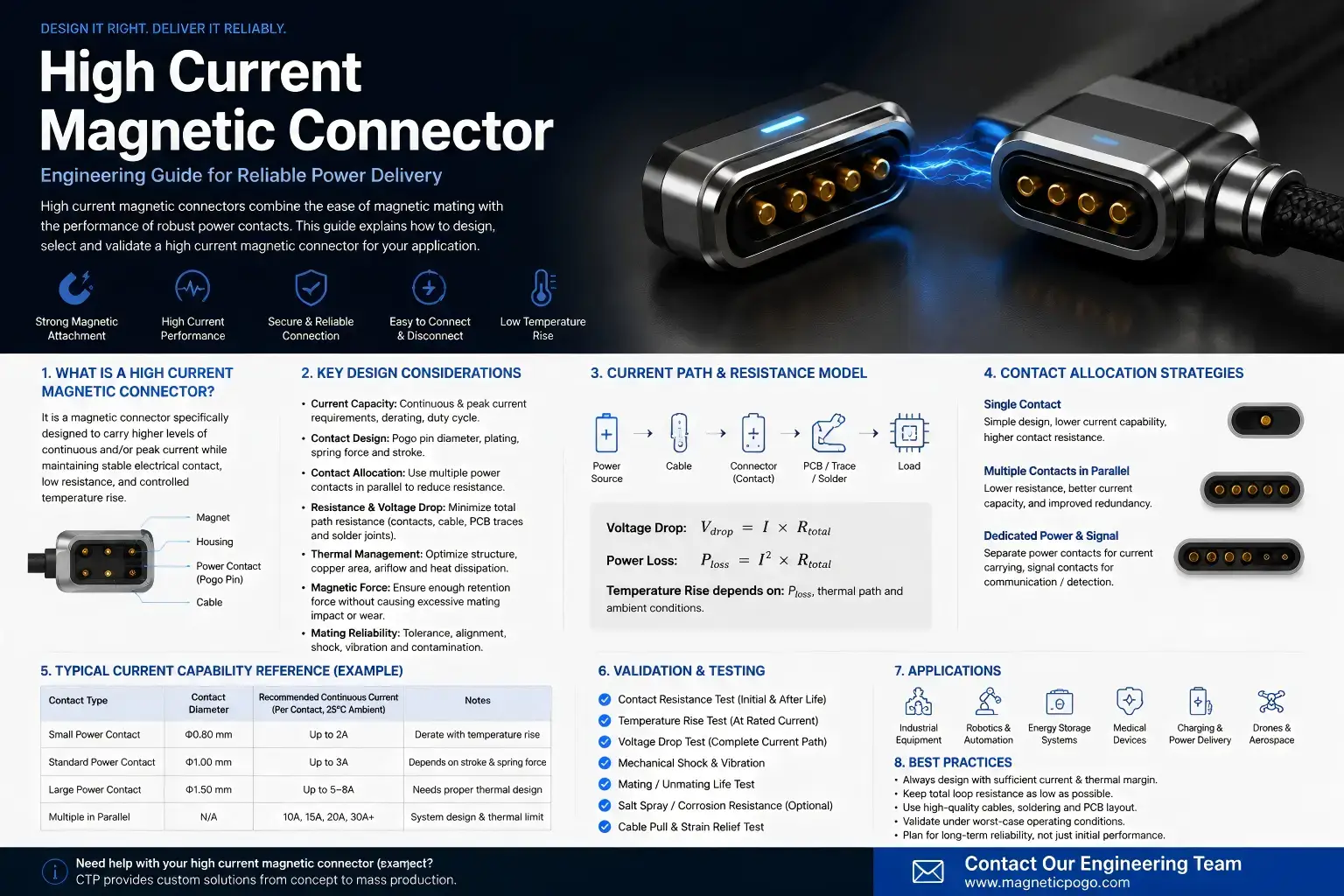
A high current magnetic connector should not be approved from a single amp rating, a room-temperature resistance value, or the rating of one pogo contact. The usable current of the finished interface depends on the assembled contact condition, total resistance, ambient temperature, duty cycle, current sharing, mating state and the temperature limits defined for the project.
For this reason, high-current capability is better treated as an operating envelope:
Current + ambient temperature + working stroke + mating state + duty cycle + lifecycle condition → validated electrical and thermal performance.
This guide explains how to qualify that operating envelope without assuming a universal current limit, contact resistance, temperature rise or lifecycle value.
What Does “High Current” Mean for a Magnetic Connector?
There is no universal current threshold that turns a magnetic connector into a “high-current” connector.
The term becomes engineering-relevant when the required electrical load makes voltage drop, resistive heating, contact condition and thermal rejection important enough that they must be explicitly controlled and validated.
A connector carrying a given current in a large open fixture may behave differently when the same interface is installed inside a compact enclosure at a higher ambient temperature. The connector geometry may be identical, but the thermal environment is not.
Likewise, a short peak may create a different thermal condition from the same current applied continuously.
Therefore, a high-current requirement should include at least:
- operating voltage and allowable variation;
- continuous current;
- peak current;
- peak duration and repetition;
- duty cycle;
- ambient temperature range;
- minimum required device voltage;
- allowed connector or system temperature;
- defined mating condition;
- expected lifecycle state.
The objective is not to find the largest amp number. It is to define a condition that can be tested and approved.
Define a Current Envelope Instead of a Single Amp Rating
A single current number hides several variables that directly affect the finished connector.
For example, the same connector may have different usable current limits under:
- different ambient temperatures;
- continuous versus intermittent loads;
- minimum versus nominal pogo-pin compression;
- different PCB or cable terminations;
- new versus aged contact surfaces;
- different numbers of power contacts connected in parallel;
- different enclosure thermal conditions.
A more useful specification format is:
Approved current = function of ambient temperature, duty cycle, mated condition and defined thermal limit.
This naturally leads to current-temperature derating rather than one universal rating.
At a lower ambient temperature, the connector may have more thermal headroom. As ambient temperature increases, less internal heat generation may be acceptable before the project temperature limit is reached.
The exact current-temperature relationship must be established by the connector design and the approved test conditions. It should not be copied from another connector with a different contact layout, termination, housing, cable or PCB structure.
Establish the Mechanical Contact Condition Before Thermal Testing
Electrical qualification begins with mechanical definition.
A spring-loaded magnetic connector can only be meaningfully tested when the installed contact condition is controlled.
The mechanical architecture should distinguish:
| Function | Primary Design Element |
|---|---|
| Initial capture | Magnetic system |
| Final alignment | Housing guides and mechanical datums |
| Final Z position | Mechanical stop and product stack-up |
| Electrical compliance | Spring-loaded contacts |
| Power path | Contacts, targets, terminations and conductors |
Working stroke is not the same as total pogo-pin travel.
The current test should use the assembled working condition defined by the product rather than an arbitrary compression selected only because the connector can physically reach it.
Where tolerance is significant, test planning should consider minimum, nominal and maximum installed compression.
This matters because:
Stack-up variation → different contact condition → different effective resistance → different I²R loss → different temperature rise.
Testing only the nominal CAD position can therefore miss a high-resistance or high-temperature tolerance corner.
Measure Baseline Resistance Before Applying High Current
Resistance measurements help establish the electrical starting condition before a thermal test.
However, engineers should distinguish between several different resistance definitions.
Mated Contact Resistance
This measurement focuses on the resistance across a defined mated contact pair or contact interface.
It is useful for understanding the connector contact condition and for comparing samples before and after environmental or lifecycle stress.
Connector Assembly Resistance
This may include contacts plus internal terminals, interconnect structures or other parts of the connector assembly, depending on the measurement points.
Complete Power-Path Resistance
A finished system can include:
Source → PCB or cable → termination → spring contact → mating interface → target → device connection → load → return path
The complete path resistance can be represented conceptually as:
Rpath = ΣRsegment
The resulting voltage drop is:
Vdrop = I × Rpath
and resistive power loss is:
Ploss = I² × Rpath
These equations explain why resistance becomes increasingly important as current rises, but they do not define an acceptable resistance or current by themselves.
IEC 60512-2-2 provides a standardized specified-test-current method for measuring resistance across mated connector contacts. IEC 60512-2-3 addresses contact-resistance variation under specified dynamic conditions.
Build a Current-Step Temperature-Rise Test
A high-current qualification should observe what happens thermally as electrical load increases.
A practical current-step test can follow this logic:
Defined sample → defined ambient → defined mating condition → current step → thermal stabilization → temperature measurement → next current step
The exact current increments, stabilization criterion, measurement locations and maximum permitted temperatures should come from the project test plan.
The purpose is to answer:
- How does connector temperature change as current increases?
- Where does the first significant hot spot appear?
- Does one sample or contact behave differently from the others?
- Does resistance change as the connector heats?
- Does the connector remain mechanically seated throughout the test?
IEC 60512-5-1 defines a connector temperature-rise test method for assessing current-carrying ability at a specified current under defined conditions.
The standard provides the test method. The project still needs to define the current, sample configuration and acceptable temperature rise.
Find the Hottest Point in the Complete Connector Interface
The visible pogo contact is not automatically the hottest point.
Possible thermal bottlenecks include:
- the mating contact interface;
- the internal pogo contact path;
- the target contact;
- a solder or welded termination;
- a crimp or wire transition;
- a narrow PCB trace;
- a cable conductor;
- a parallel-contact branch with higher resistance;
- a location surrounded by thermally insulating housing material.
A high-current test should therefore measure the complete relevant interface rather than recording only one convenient housing temperature.
A useful failure chain is:
Local resistance increase → local I²R loss → local temperature rise → further electrical or material stress.
The temperature location and timing can also help diagnose the dominant cause.
| Observed Hot Spot | Possible Investigation Direction |
|---|---|
| Mating interface | Compression, alignment, target condition, contamination, wear |
| Termination | Solder, weld, crimp, conductor preparation or local strain |
| One parallel branch | Unequal resistance or current sharing |
| PCB transition | Copper geometry, joint structure or thermal environment |
| Cable section | Conductor structure, length, routing or local damage |
How to Build a Current-Temperature Derating Curve
Room-temperature testing alone is not enough when the connector must operate across a meaningful ambient-temperature range.
IEC 60512-5-2 provides a standardized method for assessing current-carrying capacity at elevated ambient temperature.
The engineering objective is to determine how much electrical current can be used while maintaining the temperature limit defined for the connector, surrounding product and project.
A practical derating workflow is:
- Define the connector assembly and revision being qualified.
- Define the installed working stroke and mating fixture.
- Establish baseline contact or path resistance.
- Run the defined current-temperature test at the first ambient condition.
- Repeat at additional ambient conditions required by the project.
- Record the current that corresponds to the approved thermal boundary.
- Plot allowable current against ambient temperature.
- Apply the resulting operating envelope to the product specification.
The output should not be interpreted as a universal curve for every connector using the same pogo pin.
Changes in connector housing, PCB copper, wire termination, contact count, target structure, working stroke or enclosure can change the thermal result.
This is why derating belongs to the qualified connector assembly rather than to a marketing label.
Parallel Power Contacts Require Current-Sharing Validation
Using multiple contacts in parallel can be a valid architecture for a higher-current path, but equal current sharing should not be assumed.
In a simplified parallel network, the branch with lower effective resistance carries more current.
Effective branch resistance can differ because of:
- working-stroke variation;
- target flatness;
- contact resistance variation;
- PCB routing;
- termination resistance;
- surface contamination;
- temperature;
- manufacturing variation.
This produces a potentially important chain:
Unequal branch resistance → unequal current sharing → one contact runs hotter → branch resistance changes further.
The exact behavior depends on the connector and circuit, so it should be measured rather than assumed.
Trade-Off: More Parallel Contacts
Benefit: More conductive paths may distribute the required power across several positions.
Trade-off: More contacts increase routing, tolerance, current-sharing and partial-mating complexity.
A design should therefore add contacts because the complete electrical architecture requires them—not because pin count is being used as a substitute for thermal validation.
Partial Mating and Loaded Separation Are Different Electrical States
A high-current magnetic interface does not move instantaneously from open circuit to fully seated.
The mating sequence may include:
Approach → magnetic capture → first contact → partial compression → final seating → validated electrical state
During separation, the states occur in reverse, but the electrical consequences may not be symmetrical.
If substantial current is allowed while the connector is partially engaged or separating, the interface may experience additional electrical stress. Depending on voltage, current, load characteristics and contact geometry, this can include transient voltage, concentrated heating or arcing.
Therefore:
A high-current magnetic connector should not automatically be treated as a hot-swap connector.
Where loaded mating or unmating is part of the intended system, the electrical architecture may require project-specific measures such as:
- connection detection;
- defined contact sequencing;
- current limiting;
- precharge;
- controlled power enable;
- controlled shutdown before separation;
- fault detection.
IEC 60512-9-3 provides a test method for connector mechanical operation with a specified electrical load. It does not by itself establish that an arbitrary magnetic connector is safe for hot-plug use.
Repeat High-Current Tests After Mating and Environmental Stress
A new connector sample represents only the beginning of the lifecycle.
High-current validation should also determine whether electrical and thermal performance changes after the stresses relevant to the product.
Depending on the application, this may include:
- repeated mating and separation;
- representative vibration or movement;
- temperature exposure;
- moisture or contamination exposure;
- cable movement;
- production tolerance corners.
The useful comparison is:
Initial resistance / temperature → stress → post-stress resistance / temperature
Resistance drift matters because a connector that passes an initial current test may run hotter after contact surfaces, alignment or terminations change with use.
Dynamic contact measurements can also help identify disturbances that are not visible in a static resistance test.
Common High-Current Magnetic Connector Failure Modes
| Failure Mode | Possible Mechanism | Engineering Check |
|---|---|---|
| Excessive temperature rise | Electrical resistance and insufficient heat rejection under the defined load | Current-step temperature test |
| Hot termination | Local solder, weld, crimp or conductor resistance | Measure temperature and voltage drop across the termination |
| One parallel contact overheats | Unequal current sharing | Measure branch behavior where practical |
| Under-compressed contact | Worst-case tolerance increases the seated gap | Test minimum working-stroke condition |
| High spring reaction | Multiple or larger spring contacts increase total closing reaction | Check force balance and final seating |
| Partial-mating electrical stress | Current is present before full seating or during separation | Define and test the allowed electrical states |
| Resistance drift after cycling | Wear, contamination, alignment change or contact-surface change | Repeat resistance and thermal tests after endurance |
| Ambient-temperature failure | Room-temperature current rating leaves insufficient thermal margin at higher ambient | Build current-temperature derating data |
| Magnetically attached but not fully seated | Magnetic capture occurs before controlled final mechanical position | Validate mechanical stop, working stroke and mating state |
A Practical Qualification Matrix for DVT and PVT
A useful qualification matrix connects every current claim to a defined sample and operating condition.
| Test | Sample Condition | Electrical Condition | Measurement | Purpose |
|---|---|---|---|---|
| Baseline resistance | New, correctly mated | Defined resistance test condition | Contact or path resistance | Establish initial reference |
| Current-step test | Nominal assembled condition | Increasing defined current steps | Temperature and voltage drop | Identify thermal behavior |
| Minimum compression | Worst-case large seated gap | Required operating current | Resistance and temperature | Validate low-compression corner |
| Maximum compression | Worst-case small seated gap | Required operating current | Temperature, seating and structural condition | Validate high-reaction corner |
| Elevated ambient | Defined mated condition | Project current matrix | Temperature rise / current | Build derating curve |
| Parallel current sharing | All power branches active | Defined total load | Branch current or branch temperature | Detect imbalance |
| Dynamic condition | Representative movement or vibration | Defined load | Contact disturbance / resistance variation | Check operating stability |
| Loaded mating / separation | Only where required by system architecture | Defined electrical load | Electrical state and post-test condition | Validate intended switching behavior |
| Post-endurance thermal test | After project-defined mating duty | Required operating current | Resistance and temperature | Check rating retention with use |
The acceptance criteria should come from the approved project specification. A connector test method does not create a universal acceptance temperature or resistance limit.
When a High-Current Magnetic Connector May Not Be the Right Architecture
Magnetic capture can create real value when the product needs fast removable mating, blind docking or controlled breakaway.
Another connector architecture may be more appropriate when:
- a positive mechanical lock is required under substantial sustained load;
- the system requires loaded mating or breaking behavior that has not been engineered and qualified;
- a standardized high-power connector family already satisfies the electrical, mechanical and interoperability requirements;
- available packaging cannot provide adequate contact spacing, thermal path or mechanical guidance;
- the environment contains uncontrolled ferromagnetic contamination;
- the connection is effectively permanent;
- magnetic capture creates little functional advantage compared with a conventional connector.
The question is not whether magnetic connectors can carry high current.
The better question is:
Can this specific magnetic interface maintain the required electrical and thermal margin across its complete operating envelope?
What to Provide for a High-Current Engineering Review
For a useful engineering review, provide the conditions that define the power interface rather than only an amp target.
- system voltage and allowable range;
- continuous current;
- peak current, duration and repetition;
- duty cycle;
- minimum acceptable device voltage;
- ambient temperature range;
- project temperature limits;
- Pin Map and power-contact allocation;
- whether power contacts are connected in parallel;
- connector free height and intended working stroke;
- minimum, nominal and maximum seated condition where available;
- PCB, FPC, wire or cable termination;
- magnetic capture and retention requirements;
- whether current is present during mating or separation;
- environmental and lifecycle requirements;
- available 2D or 3D drawings;
- prototype and expected production quantity.
For complete cable-level power-path engineering, continue with CTP’s High-Current Magnetic Cable Solution Guide.
For the broader connector DVP&R structure, see the Magnetic Pogo Pin Connector Validation Plan.
If the connector architecture has not yet been selected, browse custom magnetic connector structures before freezing the final contact layout.
Frequently Asked Questions
What is a high current magnetic connector?
A high current magnetic connector is a magnetically assisted removable electrical interface designed for a power load that requires explicit electrical and thermal validation. There is no universal current threshold; the usable current depends on the complete connector design and operating conditions.
How much current can a magnetic connector carry?
There is no universal value. Current capability depends on contact architecture, working stroke, resistance, conductor and termination design, ambient temperature, duty cycle, thermal rejection, mating state and the acceptance limits defined for the project.
Is a low contact resistance enough to prove a high current rating?
No. Resistance is an important input, but current qualification also requires thermal testing under defined assembled and ambient conditions.
Why is temperature rise important for high current magnetic connectors?
Resistive loss increases with I²R. As current increases, relatively small resistance in a contact, termination or conductor can create meaningful local heat, so temperature must be measured under representative load conditions.
What is current-temperature derating?
Current-temperature derating defines how the allowable current changes as ambient temperature changes while maintaining the thermal limits specified for the product.
Can multiple pogo pins be connected in parallel for higher current?
They can be designed as parallel power paths, but equal current sharing should not be assumed. Resistance, working stroke, routing, target flatness, temperature and manufacturing variation can create branch imbalance.
Does stronger magnetic force improve current capacity?
Not directly. Magnets provide capture and retention. Electrical current capability depends on the conductive path, contact condition and thermal performance. Magnetic retention still needs to be sufficient to maintain the intended seated state against spring reaction and external loads.
Should a high current magnetic connector be energized while mating?
That is a system-level decision. If current can flow during partial mating or separation, the electrical consequences and required protection or sequencing should be explicitly designed and validated.
Should current testing be repeated after mating-cycle testing?
Where lifecycle is relevant, yes. Post-endurance resistance and temperature measurements help determine whether wear, contamination, alignment or surface changes reduce the original current margin.
Which standards are useful for high-current connector validation?
IEC 60512 includes connector test methods for temperature rise, current-temperature derating, contact resistance, dynamic resistance variation and mechanical operation with electrical load. The project specification must still define the applicable conditions and acceptance criteria.
Engineering Reference Sources
- IEC 60512-5-1 — Temperature Rise
- IEC 60512-5-2 — Current-Temperature Derating
- IEC 60512-2-2 — Contact Resistance
- IEC 60512-2-3 — Contact Resistance Variation
- IEC 60512-9-3 — Mechanical Operation With Electrical Load
- IEC 60512-1 — Generic Connector Test Specification
Request a High-Current Connector Engineering Review
If your project requires a removable magnetic power interface, submit the voltage, continuous and peak current, duty cycle, ambient range, Pin Map, contact allocation, working stroke, mating-state requirements, termination structure and available drawings.
Submit Your High-Current Magnetic Connector Project for Engineering Review
CTP ENGINEERING PATHS
Choose the right path for your project
Move from application requirements to a connector pair, a data-capable cable assembly, or a charging cable configuration. Final specifications are confirmed against an approved drawing and project validation plan.
Magnetic Connectors
Connector geometry, pin layout, mechanical integration and OEM/ODM review.
Engineering overview → 02Magnetic Data Cables
Power and signal allocation, cable exit, interface selection and assembly review.
Cable engineering → 03Magnetic Charging Cables
Browse the complete cable catalog and shortlist a starting structure for customization.
View cable catalog →