01
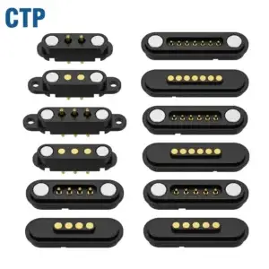
Pin Map and Contact FunctionsDefine the function of each power, return, signal, control or detection contact.

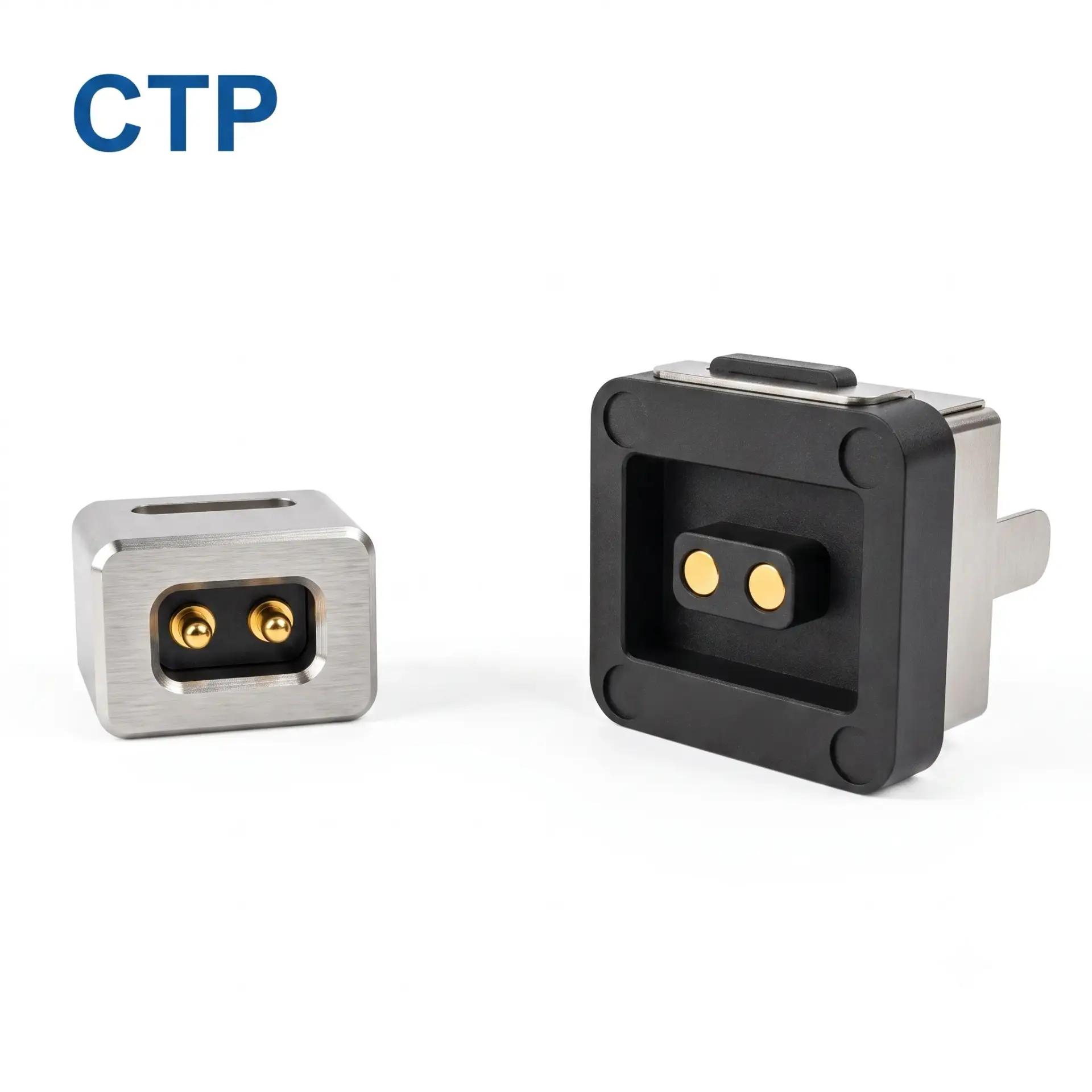
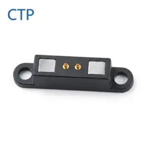
CTP is a premier, engineering-driven manufacturer specializing in high-precision magnetic pogo pin interconnect mechanisms. Our 2-Pin Magnetic DC Power Connector Set delivers robust, zero-force mating for modern low-profile, high-current hardware.
Engineered with custom permanent magnets and an intelligent polarization architecture, this system supports accurate self-alignment, foolproof directional coupling (Poka-Yoke), and comprehensive dual-circuit polarity protection. Compared to traditional barrel jacks, CTP’s magnetic solution ensures exceptional longevity, safe breakaway capabilities, and reliable power transmission.
Supports up to 12V 5A fast-charging ratings on the interconnect interface, engineered specifically for controlled voltage-drop performance.
Rigorously tested to withstand 20,000+ continuous mating cycles while maintaining stable contact resistance.
Utilizes premium NdFeB permanent rare-earth magnets to automatically guide docking and block incorrect reverse pairing.
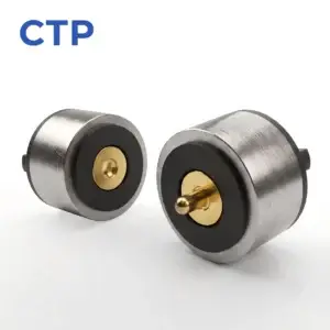
CTP 2-Pin Magnetic DC Power Connector — Male Part (Plug)
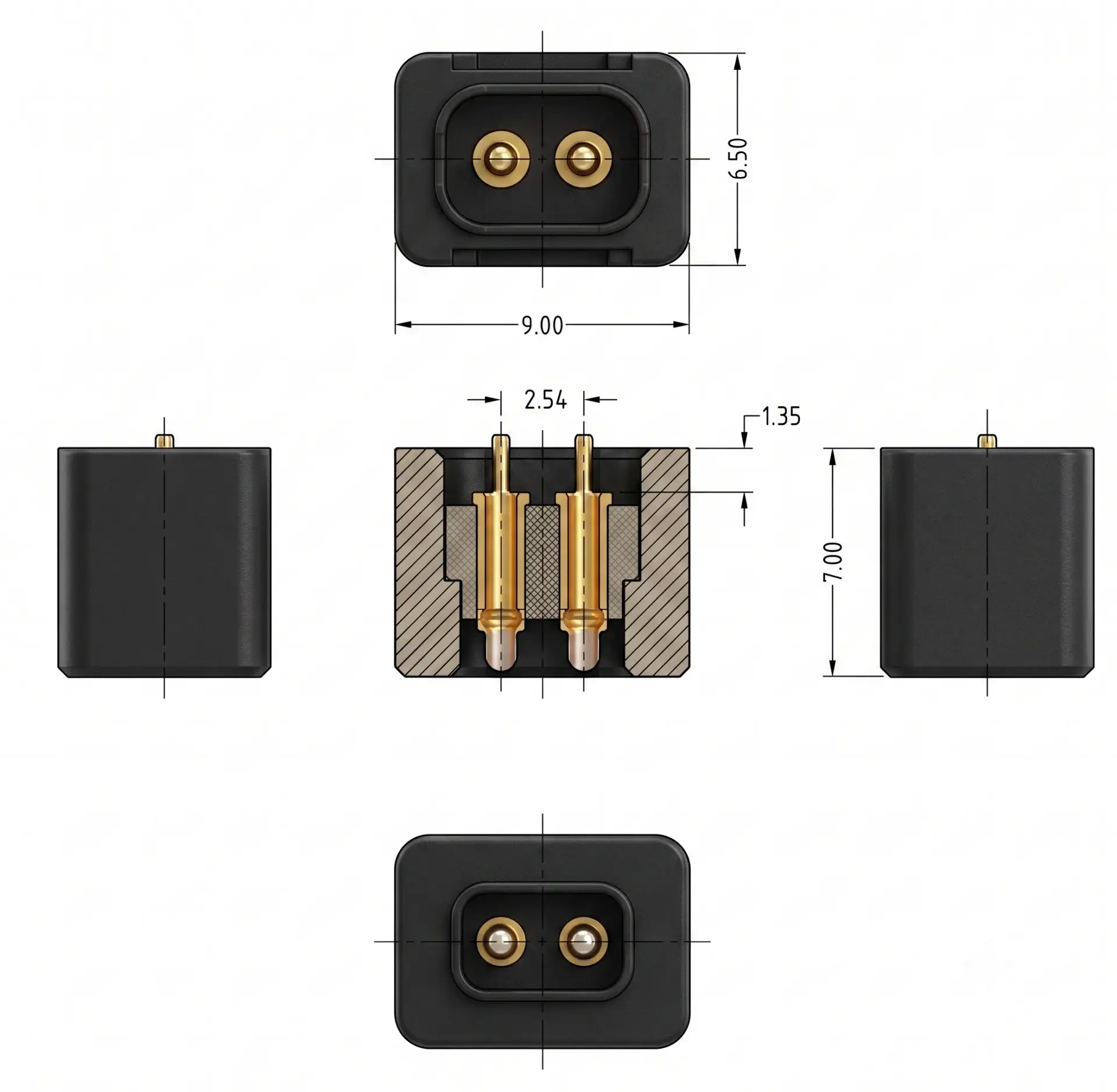
| Rated Voltage & Current | 12V DC / 5.0A Max (High-Current Fast Charging) |
|---|---|
| Contact Force | 120g ± 20% at 1.0 mm working stroke |
| Contact Resistance | ≤ 50 mΩ (Low-Resistance Interface) |
| Mechanical Longevity | ≥ 20,000 Mating Cycles |
| Target Applications | Smart LED Lighting, Precision Wireless Mice, Weatherproof Outdoor Cameras, IoT Peripherals |
CTP 2-Pin Magnetic DC Power Connector — Female Part (Receptacle)
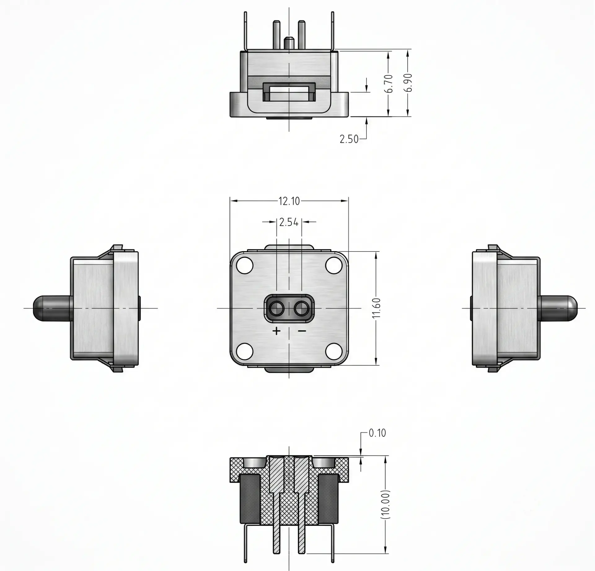
| Rated Voltage & Current | 12V DC / 1.0A Continuous (Cross-compatible with 5A Mating System) |
|---|---|
| Contact Resistance | ≤ 50 mΩ Max |
| Magnet Material | Premium NdFeB Permanent Rare-Earth Magnets |
| Environmental Standards | RoHS Compliant, REACH Certified, Halogen-Free (HF) |
| Target Applications | Smart LED Systems, Ergonomic Peripherals, Weatherproof Outdoor Cameras, Medical Wearables |
Accelerate your engineering process. We provide engineering DFM review and deliver tailored sample timing confirmed after engineering review.Request Instant Quote & Samples
This product page presents a CTP magnetic connector configuration for engineering reference. Final dimensions, electrical ratings, materials, magnet structure, sealing level and reliability targets are not universal values; they are confirmed against the approved drawing, installation condition and model-specific validation plan.
CTP reviews the application and prepares a drawing or specification for approval before sample production. Test scope, acceptance criteria and report format should identify the model, sample status, method, conditions, result and review date.
Yes. Customization can cover geometry, contact layout, materials, cable construction, magnetic structure, sealing and appearance. Feasibility depends on the application and approved specification.
No. Current, voltage, resistance, temperature rise and ingress-protection claims apply only to the identified model and stated test conditions.
Timing is confirmed after the drawing, materials, tooling, sample quantity, validation scope and production requirements have been reviewed.
ENGINEERING CONFIRMATION BEFORE SAMPLING
Confirm power, signal and grounding allocation for the intended device.
Confirm working stroke, alignment, mounting, retention and mating behavior.
Confirm cable exit, host interface and project-specific assembly requirements.
Use the approved drawing and agreed validation plan as the release reference.