The best pogo pin connector manufacturer should be evaluated through
engineering evidence rather than marketing claims, factory size or one
catalog specification. For a custom connector project, the supplier should
be able to demonstrate how working stroke, mating targets, magnetic
behavior, complete electrical paths, environmental conditions and
production characteristics are defined, tested and transferred into the
approved manufacturing specification. The following five standards provide
an evidence-based framework for technical supplier audits.
What Should “Best Pogo Pin Connector Manufacturer” Actually Mean?
The word “best” is frequently used in connector sourcing, but it has little
engineering meaning unless the evaluation criteria are defined.

One manufacturer may be strong in high-volume standard pogo pins.
Another may specialize in custom magnetic connectors, cable assemblies,
high-density arrays or prototype development.

Therefore, the useful question is not:

“Which factory says it is the best?”
It is:
    “Which manufacturer can provide the engineering evidence required by
    this specific interface?”


A technical audit should connect:


    Product Requirement
    →
    Engineering Specification
    →
    Validation Evidence
    →
    Production Control


If one of these links is missing, the supplier may still be able to make a
sample, but the engineering team has less evidence that the design is
understood and controlled.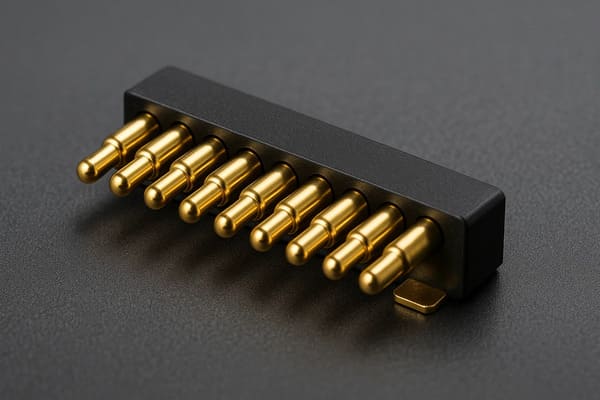
mechanical, electrical and environmental requirements rather than
appearance alone.
Standard 1: Demand Contact-Mechanics Evidence, Not Just a Pogo Pin Drawing
Spring-loaded contacts are mechanical systems as well as electrical
contacts.

The first technical audit should therefore determine whether the
manufacturer understands the complete installed contact condition.

Relevant dimensions can include:- free height;
- installed height;
- total mechanical travel;
- recommended working stroke;
- contact force at the intended stroke;
- mating-target position;
- mechanical datum position;
- PCB and housing tolerances.
Working Stroke Is a System Dimension
A simplified installed compression can be expressed as:

S = Hfree - Hseated
where:
- S = actual pogo pin compression;
- Hfree = installed free height;
- Hseated = installed height after final mechanical seating.
The supplier should not evaluate this value in isolation.

The final stroke window can be affected by:- pogo pin height tolerance;
- PCB thickness;
- solder height;
- connector housing;
- mating-target height;
- module flatness;
- mechanical-stop tolerance.
Ask for Minimum, Nominal and Maximum Conditions
A nominal CAD assembly is not enough.| Condition | Engineering Question |
|---|---|
| Minimum Compression | Is contact force and electrical stability still sufficient? |
| Nominal Compression | Does the connector operate in its intended condition? |
| Maximum Compression | Are mechanical loads still inside the approved design window? |
Total Travel Is Not the Same as Recommended Working Stroke
A pogo pin may physically move beyond its intended operating compression.

The product should normally use mechanical features to control the final
assembled position rather than repeatedly using the pogo pin as a hard
structural stop.
Ask the Manufacturer for a Force-Displacement Relationship
For projects where contact force is critical, useful evidence can include
force measurements at defined compression points.

The purpose is not to demand one universal force value.

It is to verify that:


    Defined Working Stroke
    →
    Defined Contact Force
    →
    Stable Contact Condition
The Mating Target Is Part of the Connector
Engineers sometimes qualify the pogo pin while treating the opposite target
as an unrelated PCB feature.

That creates a gap in the validation model.
The target influences:
- working stroke;
- contact force;
- wear;
- contact resistance;
- alignment;
- current distribution across multi-pin arrays.
A capable manufacturer should therefore review the pogo pin and target as
one interface.
Engineering Evidence to Request for Standard 1
| Evidence | What It Should Clarify |
|---|---|
| Connector Drawing | Critical interface dimensions |
| Working-Stroke Range | Minimum, nominal and maximum compression |
| Force Data | Contact force at defined stroke where required |
| Mating-Target Specification | Geometry, position and surface requirement |
| Tolerance Review | Installed stroke under assembly variation |
Standard 2: Audit Magnetic Behavior as a Mechanical System
A magnetic pogo pin connector contains two different systems:- a spring-loaded electrical contact system;
- a magnetic capture or retention system.
Combining them does not mean the magnet should control every mechanical
function.
Magnetic Force Is Not One Number
A technical specification should distinguish several behaviors.| Mechanical Behavior | Engineering Question |
|---|---|
| Capture Behavior | How does the connector behave during final approach? |
| Final Seating | What structure defines the final connector position? |
| Seated Retention | What normal-use loads must the interface tolerate? |
| Axial Separation | What happens during straight pull-off? |
| Peel Separation | How does the interface release from one edge? |
| Off-Axis Loading | How does cable or module rotation affect retention? |
Mechanical Datums Should Define Final Position
Magnets can assist the mating process, but the final connector position
should normally be defined by controlled mechanical geometry.
A robust function split is:
    Product Approach
    →
    Mechanical Guidance
    →
    Magnetic Capture
    →
    Mechanical Seating
    →
    Defined Pogo Stroke


This is different from allowing magnetic attraction to determine the final
compression by itself.
The Magnet Must Overcome the Complete Reaction System
For a multi-pin connector, each compressed spring creates a reaction force.

The complete mechanical design may also include:- gasket reaction;
- cable load;
- module weight;
- vibration or acceleration;
- peel forces.
The magnetic design should therefore be evaluated against the complete load
path rather than simply specifying a magnet grade.
a project-specified magnet grade Is Not a Universal Quality Requirement
Magnet grade should follow:- required capture behavior;
- retention;
- temperature;
- available volume;
- mechanical layout;
- corrosion strategy.
A manufacturer should be able to explain why a magnetic structure was
selected rather than presenting one grade as automatically superior.
Partial Mating Must Be Evaluated
Magnetic attraction begins before the connector has necessarily reached its
final working position.

Engineers should therefore consider:- tilted attachment;
- partial pogo pin compression;
- only some contacts engaging;
- debris preventing full seating;
- electrical behavior before final validation.
Magnetic attachment should not automatically be interpreted as proof of a
valid electrical connection.
Engineering Evidence to Request for Standard 2
| Evidence | What It Should Clarify |
|---|---|
| Magnet Layout | Polarity and mechanical architecture |
| Retention Measurement | Defined measurement direction and condition |
| Spring-Reaction Review | Relationship between contact force and retention |
| Mechanical Datums | What defines final X-Y-Z position? |
| Partial-Mate Review | Behavior before complete seating |
Standard 3: Demand Electrical Evidence for the Complete Path
One of the easiest ways to identify weak technical communication is a
manufacturer that answers:

“How much current can this connector carry?”
with only one number.
Current capability is a thermal-system question.A complete path may include:
    Source
    →
    PCB / Cable
    →
    Termination
    →
    Pogo Pin
    →
    Contact Interface
    →
    Mating Target
    →
    Device PCB
    →
    Load
A simplified path resistance is:
    Rpath =
    Rcable/PCB +
    Rtermination +
    Rpogo +
    Rinterface +
    Rtarget +
    Rdevice
Voltage drop is:
Vdrop = I × Rpathand resistive power loss is:
Ploss = I² × RpathAsk for Voltage Drop and Temperature Rise
A strong current-validation report should identify:- connector revision;
- working stroke;
- mating target;
- termination;
- ambient condition;
- applied current;
- measurement location;
- test duration or stabilization condition;
- voltage drop;
- temperature rise.
A current number without these conditions is much less useful.Parallel Contacts Require Current-Sharing Evidence
Several pogo pins can be connected in parallel, but equal current sharing
should not be assumed.
Current distribution can be influenced by:
- contact-resistance variation;
- working-stroke variation;
- target flatness;
- module tilt;
- PCB routing;
- termination resistance.
Where parallel contacts are important to the power architecture, the
manufacturer should support validation of the complete array.
High-Speed Data Requires Channel Evidence
A pogo pin connector with many contacts is not automatically a high-speed
connector.
Signal performance can depend on:
- signal-to-return allocation;
- contact pitch;
- contact geometry;
- PCB launches;
- reference-path continuity;
- FPC or cable structure;
- crosstalk;
- complete channel length.
Therefore:


    Pin Count ≠ Bandwidth.
A Metal Housing Does Not Automatically Prove EMI Performance
Conductive housing can contribute to shielding, but complete EMC behavior
can also depend on:- housing continuity;
- ground connection;
- gaps and apertures;
- PCB reference planes;
- signal-return paths;
- cable shielding;
- system grounding.
The manufacturer should not infer high-speed or EMI performance solely from
the presence of a metal enclosure.
Engineering Evidence to Request for Standard 3
| Evidence | What It Should Clarify |
|---|---|
| Resistance / Voltage-Drop Test | Complete electrical path under defined conditions |
| Temperature-Rise Test | Thermal behavior at the required current |
| Parallel-Contact Test | Current sharing where multiple contacts are used |
| Signal Validation | Required channel performance where applicable |
| Test Configuration | Stroke, target, cable, PCB and environmental conditions |
Standard 4: Require Environmental Evidence for the Exact Assembly
Environmental performance is one of the areas where connector marketing
can become overly simplified.

A manufacturer may advertise:- waterproof;
- IP68;
- salt resistant;
- sweat resistant;
- high temperature;
- chemical resistant.
These are different engineering requirements.An IP Rating Is Not a Generic Pogo Pin Property
Environmental protection belongs to a defined and tested connector or
product configuration.
The sealing boundary may include:
- pogo pin feedthroughs;
- connector housing;
- housing-to-device joint;
- gaskets;
- potting;
- mating target;
- PCB, FPC or cable termination.
A flat contact surface or insert-molded structure alone does not prove a
specific IP rating.
Ask Which State Was Tested
| Connector State | Engineering Question |
|---|---|
| Fully Mated | Was the connector completely seated during testing? |
| Unmated | Are exposed contacts also required to meet an environmental condition? |
| Partially Mated | What happens before the sealing boundary is fully established? |
Water Resistance Does Not Prove Corrosion Resistance
A connector that prevents water from entering the enclosure can still have
exposed contacts affected by:- salt;
- sweat;
- cleaning residue;
- industrial fluids;
- corrosion products.
These exposures should be specified separately where relevant.Environmental Testing Should Include Post-Test Performance
A useful environmental report should not always stop at:

“No visible water entered.”

Depending on the product requirement, post-test checks may include:- contact resistance;
- voltage drop;
- temperature rise;
- pogo pin movement;
- working stroke;
- corrosion;
- housing condition;
- magnetic retention.
Engineering Evidence to Request for Standard 4
| Evidence | What It Should Clarify |
|---|---|
| Environmental Test Report | Exact connector or assembly tested |
| Test State | Mated, unmated or another defined configuration |
| Sealing Boundary | Which interfaces provide environmental protection? |
| Post-Test Inspection | Electrical and mechanical condition after exposure |
| Material Compatibility | Actual project-relevant fluids or environments |
Standard 5: Audit the Transfer from Engineering Sample to Production
The final engineering standard is not factory size.

It is whether the manufacturer can translate the validated design into a
repeatable production process.

A working sample demonstrates:

the design can work.

A pilot run should help demonstrate:

the process can reproduce it.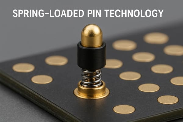
requirements into measurable manufacturing controls.
Create a Requirement-to-Control Matrix
| Design Requirement | Production Control |
|---|---|
| Pin Position | Dimensional inspection |
| Installed Height | Height / coplanarity control |
| Contact Force | Force test at defined stroke |
| Electrical Performance | Defined resistance or voltage-drop test |
| Magnet Orientation | Polarity inspection |
| Magnetic Retention | Defined force test where required |
| Mating Target | Geometry and surface control |
| Connector Revision | Drawing and change control |
AOI Does Not Prove Every Requirement
Automated optical inspection can help with visible assembly conditions.

It cannot automatically verify:- spring force;
- internal spring condition;
- electrical resistance;
- temperature rise;
- surface-finish adhesion;
- lifecycle performance;
- magnetic force in every direction.
The production plan should therefore assign the correct method to each
critical requirement.
Tape-and-Reel Does Not Automatically Mean SMT-Ready
Packaging format and process compatibility are separate questions.

Surface-mount validation can also require review of:- PCB pad design;
- pick-up surface;
- nozzle access;
- component balance;
- coplanarity;
- reflow compatibility;
- solder paste volume;
- post-reflow installed height.
Factory Capacity Is Not the Same as Project Capacity
When evaluating production readiness, separate:


    Factory Capacity
    →
    Available Capacity
    →
    Project Capacity
    →
    Reserved Capacity


A large aggregate monthly production number does not prove that the
required capacity is available for one specific custom connector.
Pilot Production Should Evaluate Distribution, Not One Sample
Useful pilot information can include:- dimensional distribution;
- contact-force distribution;
- electrical-test distribution;
- assembly yield;
- rework rate;
- traceability;
- process stability.
This is a stronger production-readiness signal than factory scale alone.The Five Engineering Standards at a Glance
| Audit Standard | Core Question | Evidence to Request |
|---|---|---|
| 1. Contact Mechanics | Is the pogo pin operating inside a controlled stroke and force window? | Drawing, stroke, force and tolerance data |
| 2. Magnetic Architecture | Are capture, retention and final seating independently defined? | Magnet layout and force-condition data |
| 3. Electrical Performance | Is power or data performance validated through the complete path? | Voltage-drop, thermal and channel evidence |
| 4. Environmental Performance | Does the evidence apply to the exact connector configuration? | Test state, sealing boundary and post-test data |
| 5. Production Transfer | Can the validated design be repeatedly manufactured? | CTQ controls, pilot data and process evidence |
Use an Evidence Matrix Instead of Marketing Claims
During the supplier audit, create one row for every important claim.| Supplier Claim | Evidence Question |
|---|---|
| High Current | Under what stroke, target, ambient and thermal conditions? |
| Long Life | What connector revision, test condition and failure criterion? |
| Waterproof | What complete assembly and state were tested? |
| High-Speed Data | What complete channel architecture was validated? |
| High Magnetic Force | Which direction and connector condition were measured? |
| Automated Production | Which CTQs are automatically controlled or inspected? |
| High Capacity | How much project-specific capacity is actually available? |
Red Flags During a Technical Manufacturer Audit
Be cautious when a manufacturer:
- recommends a connector before reviewing the Pin Map and mechanical envelope;
- cannot distinguish total travel from recommended working stroke;
- uses magnetic force as the only explanation for final connector alignment;
- quotes current without thermal-test conditions;
- uses pin count to claim data bandwidth;
- claims an IP rating without identifying the tested configuration;
- quotes lifecycle without defining working stroke and failure criteria;
- uses AOI as proof of all connector quality characteristics;
- treats tape-and-reel packaging as proof of SMT compatibility;
- uses total factory output as guaranteed capacity for your project.
Technical Audit Checklist for a Pogo Pin Connector Manufacturer
| Audit Question | Expected Engineering Response |
|---|---|
| What is the recommended working stroke? | A defined operating range tied to the connector design |
| What happens at minimum and maximum stack-up? | Tolerance analysis or representative test evidence |
| How is final position controlled? | Mechanical datums and stops |
| How is magnetic retention measured? | Defined direction, setup and condition |
| How is current capability validated? | Complete-path voltage-drop and temperature-rise evidence |
| How is data capability validated? | Channel-level evidence where required |
| Which assembly received the environmental test? | Exact model, revision and tested state |
| How are CTQs transferred into production? | Inspection and process-control plan |
| How was pilot production evaluated? | Population data rather than one selected sample |
What Should You Send Before Requesting Engineering Evidence?
The manufacturer cannot provide project-specific evidence without knowing
the product requirements.| Project Input | Information to Provide |
|---|---|
| Application | Charging, docking, module, service, test or another interface |
| Mechanical Envelope | Available X, Y and Z space |
| Pin Map | Power, return, detection and signal functions |
| Working Stroke | Available or target compression range |
| Electrical Conditions | Voltage, continuous current, peak current and duty cycle |
| Signal Requirement | Required control or communication channel |
| Magnetic Behavior | Capture, retention and separation requirements |
| Environment | Temperature, moisture, dust, sweat, salt or chemicals |
| Lifecycle | Expected mating profile and end-of-life criteria |
| Production | Prototype, pilot and expected mass-production volume |
| Project Files | 2D drawing, 3D assembly, PCB layout or enclosure model |
Frequently Asked Questions
How do I identify the best pogo pin connector manufacturer?
Evaluate whether the manufacturer can provide project-specific evidence for
contact mechanics, magnetic behavior, electrical performance, environmental
conditions and production transfer rather than relying only on factory size
or catalog claims.
What should I ask a pogo pin connector manufacturer before ordering?
Ask for the recommended working stroke, mating-target requirements,
mechanical datums, electrical test conditions, magnetic measurement method,
environmental-test configuration and production-control method.
Does a stronger magnet mean a better magnetic pogo pin connector?
No. Magnetic strength should follow the required capture, retention,
separation, temperature and mechanical architecture. Excessive attraction
can introduce other mechanical trade-offs.
Does a project-specified magnet grade mean a magnetic connector is higher quality?
Not automatically. Magnet grade is only one design variable and should be
selected from the complete magnetic, thermal and mechanical requirements.
How should pogo pin current capability be verified?
Review voltage drop and temperature rise through the complete conductive
path under representative working stroke, target, termination and ambient
conditions.
Can a multi-pin pogo connector support high-speed data?
Potentially, but pin count alone does not prove bandwidth. Signal and
return allocation, geometry, PCB transitions, cable structure and the
complete channel must be considered.
How do I verify an IP68 pogo pin connector claim?
Ask which exact connector or complete assembly was tested, its revision,
mating state, sealing configuration, applicable test condition and
acceptance criteria.
Is insert molding enough to make a pogo pin connector waterproof?
No. Insert molding can form part of the sealing architecture, but ingress
protection depends on the complete connector and enclosure boundary.
Is AOI enough to prove pogo pin manufacturing quality?
No. AOI can inspect selected visible characteristics, while force,
electrical, magnetic, thermal and lifecycle requirements may require
different inspection or test methods.
Does tape-and-reel mean the pogo pin connector is SMT-ready?
No. SMT compatibility also depends on PCB pad geometry, pick-up design,
coplanarity, solder process, reflow compatibility and installed height.
How do I know whether a prototype can scale to mass production?
Review pilot-production distributions, CTQ controls, process capability,
yield, inspection methods and whether the production process can reproduce
the approved connector without exceptional manual adjustment.
Is the largest pogo pin factory automatically the best manufacturer?
No. Factory scale is only one sourcing factor. Engineering fit, validation
evidence, process control and project-specific manufacturing capability are
more useful indicators for a custom connector program.
Request a Pogo Pin Connector Engineering Review
Explore

    CTP custom magnetic connector solutions

for removable charging, docking and modular product interfaces.

Review

    CTP pogo pin connector solutions

for project-specific spring-contact layouts and mounting structures.

Learn more about CTP engineering and manufacturing capabilities on the

    About Us page
. Submit your connector envelope, Pin Map, working stroke, mating target,
voltage, current, signal requirements, magnetic behavior and
environmental conditions to CTP for an engineering review.
The review can be used to define the connector geometry, mechanical
interface and project-specific validation requirements before the
production specification is frozen.
Final current capability, signal performance, ingress protection,
lifecycle and production capability should be confirmed against the
approved connector revision and defined validation conditions.