
The magnetic head clicks into place, but the device shows no charging response. The click tells you that the parts are attracted to each other. It does not confirm the electrical pin assignment, the contact’s seated position or the behaviour of the power source.
If a magnetic connector is attached but not charging, start with the complete approved connection: source, cable, magnetic interface and device-side mate. CTP supplies guided two-contact heads, slim magnetic leads and four- or six-contact assemblies for different device requirements. A matching assembly gives the project a defined route to review; a similar-looking replacement can leave important differences hidden.
Can the magnetic charging head attach without its contacts seating correctly?
Yes. Magnetic attraction and electrical contact are related parts of the assembly, but they are not the same function. A housing lip, debris or a mismatched mating shape can keep the contacts from reaching their intended position even though the head stays attached.
A guided two-contact head needs its matching receiving geometry
Our guided-head two-contact cable, CTP-MCC-2P-A03, has a rectangular molded head with a projecting mating tongue and two visible contact positions. It is a useful format to consider where the product needs a deliberately guided attachment shape.
The receiving part must be developed for that geometry. A lookalike opening is not a defined mate, and stronger attraction will not correct an obstruction. For an OEM accessory, keeping the head and receiver in the same drawing makes that physical relationship easier to approve.
A slim two-contact cable offers another mating arrangement
The CTP slim rectangular two-contact cable, CTP-MCC-2P-SR-A16, uses two contacts in a linear arrangement with a separate device-side mating component. It gives the designer a different head proportion for a compact charging position.
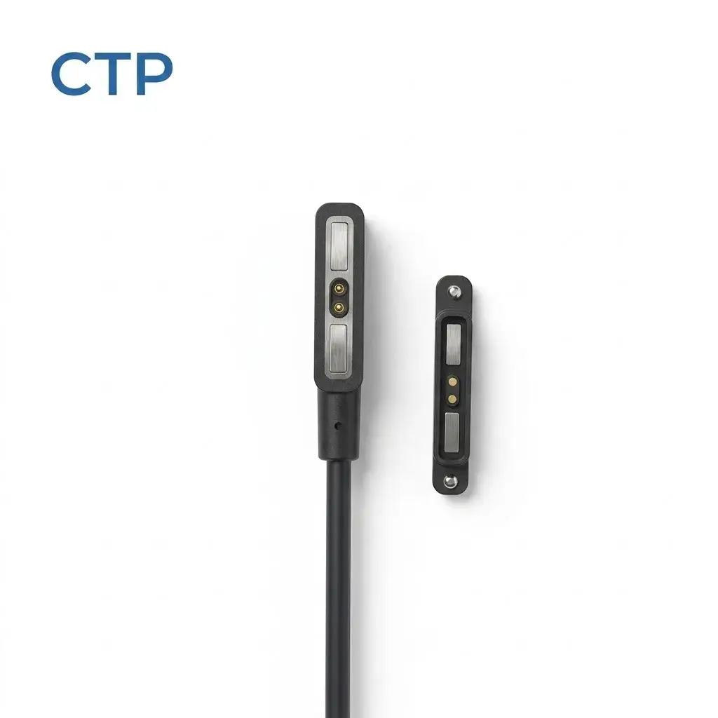
For a small desk accessory, the slim outline may fit the available edge neatly. If the device does not charge, confirm that the specified pair is being used before assuming the cable has failed. The head’s shape alone cannot identify its polarity or electrical allocation.
Does a compatible-looking magnetic cable have the right pin assignment?
A replacement cable may attach to the device while placing the wrong functions against its contacts. Contact count and magnetic attraction are not a complete compatibility specification. Use the approved wiring and part definition, particularly when several accessories have similar exterior shapes.
A four-contact wearable lead needs all four positions defined
Our four-contact wearable cable, CTP-MCC-4P-A03, uses a compact flat charging head with four electrical contact positions. It is a product option for a wearable or other detachable interface whose circuit needs that arrangement.
Those contacts may have different assigned roles. The project drawing should identify them rather than assume that every position is a charging-power contact. For a wearable brand supplying replacement leads, a clear part identity helps avoid treating several similar accessories as interchangeable.
Consider an instrument family with a basic device and a version that adds detection or control functions at the interface. Even if their housings are close in size, the approved cable allocation can differ. The correct replacement is the one defined for that device version.
Is the source providing what the charging circuit expects?
A magnetic connector does not perform the charging control by itself. The source, cable wiring and device circuitry need to support the intended arrangement. Likewise, a familiar source-end plug does not prove that a particular fast-charging mode or communication function has been implemented.
For a project sample, review the source and the device’s expected input with the approved assembly. Do not bridge contacts or improvise a pin assignment to force a charging response. A controlled check by the responsible engineering team is more useful than repeatedly reconnecting an unidentified lead.
If an approved spare assembly is available, comparing it in the same intended setup can help narrow the question. Keep the device and source unchanged while the responsible team checks the identified replacement lead. Then record whether the symptom follows the lead or remains with the device-side connection. For the guided two-contact format, include a clear view of the tongue entering its matching receiver. For the four-contact wearable lead, keep the device version with the cable identity. This gives the manufacturer specific information to review without treating every charging failure as a generic cable fault.
Manufacturer troubleshooting guidance often separates the cable, contact condition and power source; Garmin’s charging checks are one device-specific example. Their care instructions apply to the products named there, rather than approving a cleaning chemical or charger for every magnetic interface.
A six-contact equipment cable should be reviewed as a complete supplied part
The CTP six-contact equipment cable, CTP-MCC-6P-DR-A01, uses a three-by-two dual-row interface. It is offered for custom medical-equipment projects, with the contact functions, cable construction and integration requirements defined for the actual device.
For a portable instrument, the extra assigned paths may be useful for the agreed circuit. They do not make the cable universally compatible with medical devices or establish medical approval. The complete assembly and matching receiver must be identified when a sample or replacement is reviewed.
CTP manufactures custom magnetic connectors and finished cables, so the device-side mate and the supplied lead can be discussed together. Our OEM and ODM product scope includes defining that connection around the customer’s circuit and installation.
Our magnetic cable assembly inspection article also explains what to check when identifying and reviewing a supplied lead.
When a head attaches without charging, keep the investigation tied to the exact part pair, source and device version. A photograph of the seated connection and the approved wiring definition are a much better starting point than choosing the strongest magnet or another lead that happens to fit.

