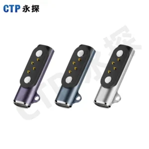
A custom connector conversation is easier when it starts with the device you want to build. Perhaps it is a handheld instrument that should drop neatly into a charging dock. Perhaps it is a removable control accessory that needs power and several other electrical paths through one small interface.
Our magnetic connectors and cable assemblies offer different ways to create that connection. A custom magnetic connector RFQ can begin with a product sketch, the intended functions and the space available. From there, the contact count, mounting style and cable format become choices you can compare against the product itself.
A magnetic connection can make attachment feel more natural
The magnetic elements assist the two parts as they approach and help retain the seated connection. Spring-loaded contacts provide the electrical pressure against their matching targets. Together with the housing, these elements create an interface that can be developed around the product’s attachment action.
For a desk accessory, that might mean bringing a small head toward a clearly positioned contact area. For a docked instrument, the housing can guide the instrument into its resting position while the magnetic interface assists the connection. The practical appeal is convenient attachment within a defined device arrangement.
Our range includes connector components, matching pairs and complete cable assemblies. That gives you a choice about how much of the connection belongs in one supplied item. A team designing its own internal harness may prefer a connector pair; another project may benefit from a cable that already includes the required end formats.
Two contacts keep a simple interface focused
The CTP two-contact magnetic connector, CTP-MPC-2P-SR-MB-A01, has a single-row contact face and a mounting ear on each side. Each ear includes a through-hole for the product-specific installation.
Mounting ears provide clear attachment features
A dock or enclosure can use these features as part of its mechanical layout. The connector body has defined points to attach to the product, while the spring contacts serve the electrical interface. That separation helps the designer bring the connector and housing together without treating the contact tips as the main structural support.
For an interface that needs two assigned electrical paths, the short contact row can keep the target area simple. Its usefulness comes from matching that limited scope to the circuit. If the product also needs a separate detection or control path, a connector with additional contacts becomes the more relevant comparison.
Five contacts offer more room for a custom device circuit
Our five-contact magnetic connector with mounting base, CTP-MPC-5P-SR-MB-A01, arranges five spring contacts in a line. The wider base includes through-holes, and magnetic features sit beside the contact row.
A mounting base can fit a dedicated accessory location
A product with a planned connection pocket can consider the whole base alongside its enclosure supports. The five paths may be assigned to power, reference and other required functions according to the circuit. The connector creates the paths; the electronics determine the supported behavior.
Imagine a small control accessory that should be recognized when attached. A separate assigned connection may support the device’s detection circuit alongside the power paths. A five-contact layout gives the design team more positions to define without moving immediately to a much larger interface.
For the RFQ, it is useful to show whether the project needs the spring-contact half, the target half or a complete pair. Those are different supplied items. Describing the desired arrangement clearly makes the proposed product easier to understand and the options easier to compare.
Eight inline positions can bring several functions to one edge
The CTP eight-contact single-row pair, CTP-MPC-8P-SR-MH-A01, combines a pogo side, flat target side and mounting ears with through-holes. Its long inline shape can suit a device or module with a defined contact edge.
For a removable instrument module, that shape can keep several assigned paths together along one side. The board and enclosure can be arranged around a recognizable interface instead of several unrelated connections. The matching halves are considered as parts of the same contact arrangement.
A larger contact count is useful when the circuit needs those positions. It does not set the current or communication capability by itself. For your product, the electrical map and required operating condition give the connector a specific job.
A dual-row pair offers another way to use a limited area
Our fourteen-contact dual-row magnetic connector, CTP-MPC-14P-DR-A01, uses a seven-by-two arrangement. It brings more positions into a rectangular interface rather than extending them all along a single line.
Seven pairs of contacts give a more involved module room to connect
A removable module with several assigned control and signal functions may benefit from that grouped pattern. The spring-contact half and flat target half provide a defined pair to integrate with the device. The two-row arrangement can be compared directly with the area available on the module.
This is one of the advantages of choosing from several contact layouts. A narrow eight-contact row and a fourteen-contact rectangular pair use space differently. The best starting point follows the product’s contact needs and available shape, rather than choosing a count first and forcing the housing around it.
A cable assembly can bring the connection together
The CTP four-contact USB-C magnetic cable, CTP-MCC-4P-USBC-DATA-01, includes a USB-C plug, cable, magnetic head and matching PCB-mount connector. It gives the product team a familiar source-end format and a custom magnetic interface at the device.

For a compact desktop product, that can make the accessory arrangement easier to picture. The cable reaches the source, the magnetic head meets the device and the matching board part sits within the electronics. Cable length, outlet direction and conductor arrangement can be developed around that route.
The supported functions depend on the approved circuit and USB-C wiring. The plug shape alone does not promise a particular charging protocol. The benefit is the coordinated assembly format, with a clear connection route from the source end to the product.
A custom magnetic connector RFQ can stay close to the product idea
One helpful distinction is where your own assembly work begins. A connector pair leaves the internal board or harness connection within the device design. A finished cable includes a defined lead and opposite end as part of the assembly. Neither scope is automatically better; each fits a different product development approach.
| Product direction | Connection format worth exploring |
|---|---|
| A dock with its own internal wiring | A connector component or matched pair with suitable mounting features |
| A device with a familiar external source plug | A USB-ended magnetic cable and corresponding device-side interface |
| A removable module with several functions | An inline or dual-row pair with the necessary assigned contact paths |
For an equipment maker developing a compact charging stand, the two-contact mounting-ear design may let the contact area remain small while the stand provides support. If the next product version also needs an identification function, the five-contact mounting-base design gives the circuit more positions to work with. The choice follows a useful device function, rather than a general preference for more pins.
A different project may already have a USB-C source connection in mind. The four-contact cable brings that end format into the same discussion as the magnetic head and board-side mate. This can make the intended accessory easier to describe and easier to evaluate as a complete route to the device.
Clear supply scope also helps a buyer compare proposals fairly. A price for one connector half describes a different item from a cable with both end formats and a matching board connector. Naming the item you want makes the commercial discussion more relevant to the product.
You do not need to turn an early product idea into a long generic checklist. A useful starting description shows the device, the two mating parts, the available connector area and the electrical functions the interface should carry.
A simple view of the intended attachment action is valuable too. A device placed into a cradle, a cable attached from the side and a removable module held inside an enclosure create different connection requirements. Showing that action gives the contact and mounting discussion a real purpose.
The custom magnetic connector guide compares the broader choices. Our product range provides concrete examples of the different contact counts, housings and cable formats available to explore.
For a straightforward two-path connection, the mounting-ear design may be a useful starting point. For additional assigned functions, the five-contact base or eight-contact pair offers another route. A larger dual-row pair or complete magnetic cable can suit a different product altogether. Begin with the connection you want the user to experience, and the RFQ can describe a part that belongs to that device.