Choosing a custom magnetic data cable manufacturer should not begin with unit price, catalogue photos or the number of contacts on the connector. For an OEM device project, the real question is whether the supplier can translate the product requirement into a controlled magnetic mating interface, cable assembly, Pin Map, prototype and repeatable production specification.
A magnetic data cable is more than a cable with a magnetic head. The finished assembly may include spring-loaded contacts, magnets, mechanical locating features, cable conductors, shielding, strain relief, overmolding and an opposite-end termination such as USB-A, USB-C, bare wire, PCB or another custom interface.
For that reason, supplier selection should follow a development sequence:
Requirement Definition → Interface Engineering → Electrical and Data Definition → Prototype Validation → Production Control.
This guide explains what OEM engineers, buyers and project managers should review before selecting a custom magnetic data cable manufacturer.
First Decide Whether the Project Actually Requires a Custom Magnetic Data Cable
Customization is useful when the device has interface requirements that cannot be satisfied reliably by a standard cable assembly.
A custom development route may be appropriate when:
- the device uses a proprietary magnetic mating interface;
- blind mating, quick release or controlled orientation is required;
- the cable must carry both power and defined signal or data functions;
- connector size, shape or cable outlet direction is constrained by the enclosure;
- the device-side interface requires a custom PCB, FPC or target-contact structure;
- cable length, conductor arrangement, shielding or termination is project-specific;
- the cable will experience repeated mating, bending, pulling, vibration or environmental exposure.
If the application only requires a simple temporary power connection and an existing cable already meets the mechanical, electrical and production requirements, a standard product may be more appropriate.
Customization should solve a defined interface problem. It should not add complexity without creating engineering value.
Evaluate Whether the Manufacturer Develops Around the Project
A custom magnetic data cable project should begin with questions, not only with a product catalogue.
A capable manufacturer should first clarify what the cable has to do inside the finished product.
| Evaluation Area | What to Look For | What Is Not Enough | Why It Matters |
|---|---|---|---|
| Requirement understanding | Questions about device interface, mating direction, space and cable function | Sending similar product photos only | Determines whether the project requirement is translated correctly |
| Mechanical engineering | Connector geometry, cable exit, mechanical guidance, tolerance and anti-misconnection review | “We can customize it” without defining how | Controls fit, mating and installed stability |
| Electrical engineering | Pin Map, power path, signal requirements, conductor and shielding definition | “Supports charging and data” | Determines whether the electrical function is actually defined |
| Prototype validation | Clear prototype objectives and problem-correction process | Device powers on once | Exposes design risks before production |
| Production control | Controlled drawings, inspection, traceability and change management | General promise that volume production is available | Determines repeatability after sample approval |
If a supplier cannot explain which project information is missing, the quotation may be based on assumptions that later change during prototyping.
Review the Complete Magnetic Mating Interface, Not Only the Cable Head
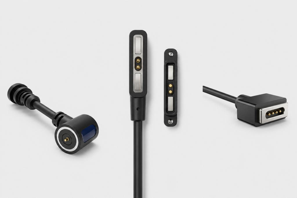
Many magnetic data cable problems originate at the interface between the cable-side magnetic head and the device-side mating structure.
A sample may show electrical continuity while still having insufficient alignment margin, poor cable routing or unstable contact compression.
The complete interface should therefore be reviewed before the cable drawing is frozen.
1. Does the Connector Shape Fit the Available Device Space?
Round, linear, rectangular, recessed and other connector shapes create different packaging and mating conditions.
The engineering review should confirm:
- connector width, length and thickness;
- clearance to the product enclosure;
- mating-face location;
- cable outlet direction;
- device-side mounting structure;
- available PCB or FPC area.
A reference photograph cannot replace dimensional constraints.
2. Is the Mating Method Clearly Defined?
The project should define how the two halves approach and reach the seated condition.
Possible architectures include direct face-to-face mating, recessed docking, guided linear mating or another product-specific structure.
The important engineering distinction is:
Magnetic capture ≠ mechanical seating ≠ valid electrical connection.
Magnets can assist capture and retention, but final position should be controlled by the connector housing, guide features, mechanical datums or stops where precise contact alignment is required.
3. Does the Interface Need Orientation Control or Anti-Misconnection Features?
If the cable cannot be connected in every orientation, the product should define how incorrect mating is prevented.
Possible methods include:
- asymmetric connector geometry;
- keying features;
- mechanical locating surfaces;
- magnetic polarity arrangement;
- electrical detection or identification where required.
The correct solution depends on the application. The supplier should understand the user or machine mating action before finalizing the connector geometry.
4. Is the Cable Exit Compatible with the Installed Routing?
A correct connector head can still fail as a cable assembly if the cable outlet conflicts with the device installation.
Review:
- straight, side or angled cable exit;
- available bending space;
- strain-relief geometry;
- installed cable routing;
- expected pull and side-load direction;
- movement or repeated flexing near the connector.
A poor routing condition can create:
Cable preload → connector-head torque → partial seating or peel load → contact instability.
This is why cable routing should be part of supplier selection rather than a later mechanical detail.
5. Has the Device-Side Target and Tolerance Stack Been Reviewed?
The mating target, PCB position, housing structure and connector installation tolerances affect the final contact condition.
For a spring-loaded magnetic interface, the supplier should distinguish the approved working condition from the total available pogo-pin travel.
Working stroke is determined by the installed product stack-up.
The design should consider minimum, nominal and maximum assembled conditions where tolerance variation can affect seating or contact compression.
6. Is Magnetic Force Being Defined Correctly?
Stronger magnetic attraction is not automatically better.
The project should distinguish:
- capture behavior;
- seated retention;
- axial separation;
- peel separation;
- off-axis load.
More magnetic retention may improve holding margin, but it may also increase removal force, closing impact or cable loading.
A manufacturer should therefore ask how the product is connected and removed rather than simply proposing the strongest available magnetic structure.
“Charging and Data” Is Not a Complete Electrical Specification
One of the most common RFQ descriptions is:
“We need a magnetic cable that can charge and transfer data.”
That is a useful starting point, but it does not define the electrical architecture.
The project should identify every required contact function.
| Contact Function | Questions to Define |
|---|---|
| Power | What voltage, continuous current, peak current and duty condition apply? |
| Return / Ground | Which path completes the power or signal circuit? |
| Data / Communication | What protocol, signal type and direction are required? |
| Detection | Does the device need to detect the connected cable or accessory? |
| Identification | Does the product need to identify a module, charger or accessory? |
| Control | Are additional control or enable functions required? |
Pin count does not define data capability.
A four-contact or five-contact connector does not automatically establish USB compatibility, signal bandwidth or a specific communication protocol.
The complete channel must include:
Source interface → source termination → cable conductor arrangement → magnetic contacts → device-side target → PCB transition → receiving circuit.
Signal or data capability should therefore be confirmed through the complete electrical channel under the defined project conditions.
Review the Pin Map Before Selecting the Cable Structure
A magnetic data cable should have a controlled Pin Map that connects every magnetic contact to a defined conductor and device-side electrical function.
A useful mapping table may include:
| Contact ID | Electrical Function | Cable Conductor | Source-Side Termination | Device-Side Connection |
|---|---|---|---|---|
| P1 | Define function | Define core or wire ID | Define plug / terminal position | Define PCB or device node |
| P2 | Define function | Define core or wire ID | Define plug / terminal position | Define PCB or device node |
| P3 | Define function | Define core or wire ID | Define plug / terminal position | Define PCB or device node |
| Additional Contacts | Define only when required | Map each conductor | Map each source position | Map each device position |
The cable drawing, magnetic mating-face drawing and device PCB drawing should use consistent contact IDs and clearly state the viewing direction.
This is especially important because male-side and female-side contact layouts can appear mirrored.
Evaluate the Complete Power Path, Not Only a Contact Current Value
If the cable carries charging power, current capability should be evaluated through the complete conductive path.
A simplified path can include:
Power Source → Connector / Plug → Cable Conductor → Termination → Pogo Contact → Mating Interface → Target → Device PCB → Load → Return Path
Voltage drop follows the complete path resistance:
Vdrop = I × Rpath
Resistive power loss follows:
Ploss = I² × Rpath
Therefore, the supplier review should consider:
- operating and peak current;
- cable length;
- conductor specification;
- termination structure;
- contact allocation;
- working stroke;
- voltage-drop budget;
- temperature-rise validation;
- ambient and duty conditions.
A high current rating for one pogo contact does not automatically establish the current capability of the finished cable assembly.
Define Cable Construction Together with the Electrical Requirement
The cable itself should be selected as part of the electrical and mechanical system.
Depending on the project, the manufacturer may need to review:
- finished cable length;
- conductor count;
- wire gauge;
- conductor arrangement;
- shielding;
- outer jacket;
- flexibility;
- cable diameter;
- strain relief;
- overmold structure;
- opposite-end termination.
CTP’s current magnetic cable product family includes project routes with USB-A, USB-C, bare wire, PCB, FPC and other customized terminations. Final cable construction should be confirmed according to the actual electrical, mechanical and installation requirements.
The Prototype Stage Should Prove More Than Basic Continuity
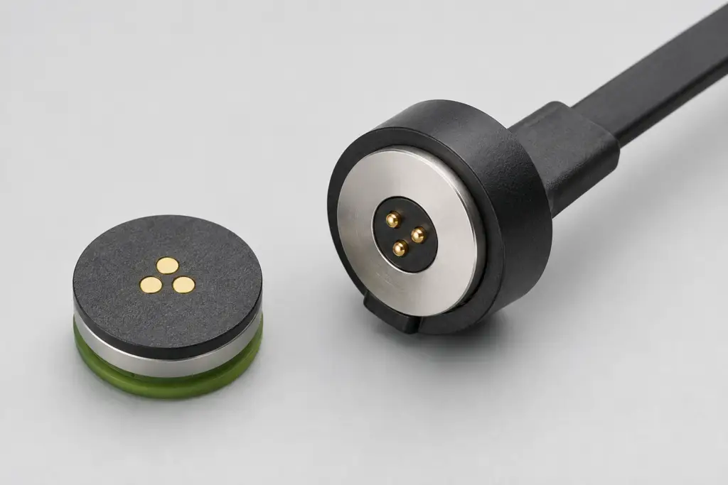
A prototype is one of the most useful opportunities to determine whether a manufacturer can turn the project definition into a working cable assembly.
Do not approve the sample only because the device powers on or communication works once.
Prototype review should consider at least four areas.
Mechanical Fit
- Does the magnetic head fit the enclosure?
- Does the interface reach the intended seated position?
- Is the cable outlet compatible with the installation?
- Is there interference during mating or removal?
Electrical Function
- Does every Pin Map function match the approved definition?
- Are charging, signal, detection or control functions operating as intended?
- Is polarity correct?
- Does the complete cable meet the required functional condition?
Mating Behavior
- Does magnetic capture occur consistently?
- Is final seating repeatable?
- Is removal controlled in the intended direction?
- Can offset or partial mating create an unintended electrical condition?
Sample Consistency
- Do multiple samples mate in the same way?
- Is cable outlet geometry consistent?
- Are contact positions and housings repeatable?
- Do electrical measurements show unusual sample-to-sample variation?
The most important supplier behavior during prototyping is not the absence of problems.
It is whether problems can be traced to a cause and corrected through a controlled design change.
Sample Approval Is Not the Same as Production Approval
A working prototype proves that one or several samples can function.
Production approval requires evidence that the same approved condition can be reproduced consistently.
Before pilot or mass production, review:
- approved cable and connector drawings;
- Pin Map and wire map revision;
- critical dimensional controls;
- incoming-material inspection;
- in-process inspection;
- final electrical test;
- mechanical or functional checks required by the project;
- lot identification and traceability;
- packaging requirements;
- engineering change control.
A manufacturer does not need to make every process dimension a CTQ.
The better question is:
Which characteristics directly protect fit, contact alignment, cable wiring, electrical function and long-term interface stability?
Those characteristics should be clearly controlled.
Check How the Manufacturer Controls Changes After Approval
Long-term OEM projects can be affected by changes that are not obvious from the finished cable appearance.
Depending on the design, relevant changes may include:
- cable conductor or jacket;
- pogo contact material or plating;
- spring specification;
- magnet or magnetic structure;
- housing resin;
- adhesive or overmolding process;
- termination method;
- critical tooling;
- assembly process;
- inspection method.
The supplier and customer should define how engineering-impacting changes are reviewed, documented and revalidated before they enter normal production.
What Information Should You Prepare Before Requesting a Quote?
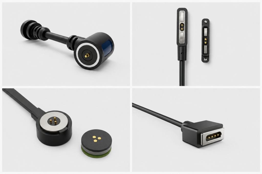
A more complete RFQ allows the manufacturer to evaluate the actual project instead of quoting from assumptions.
| Information | Preferred Input | If It Is Not Yet Available |
|---|---|---|
| Application | Device type and interface duty | Describe what the cable must connect and do |
| Mechanical Structure | 2D drawing, 3D model and installation layout | Product photos, dimensional sketch and installation description |
| Pin Map | Defined power, ground, signal, detection and control assignments | List required functions before choosing the contact count |
| Electrical Conditions | Voltage, continuous current, peak current and signal requirements | Provide the existing device or cable functional requirement |
| Data Requirement | Protocol, signal direction, channel requirement and validation scope | Describe the intended communication function |
| Cable Requirement | Length, conductor, shielding, jacket, flexibility and outlet direction | Provide installation length and movement description |
| Environment | Temperature, moisture, contamination, movement and cleaning conditions | Describe the real use environment |
| Prototype Goal | Defined items and acceptance criteria for the current build | List the most important risks the sample must prove |
| Volume | Prototype, pilot and expected production quantity | Provide the current project stage and estimated demand |
CTP’s current project-submission process accepts the application, electrical conditions, mechanical space, cable requirements, expected quantity and available drawings so the project can be routed to an existing structure, modified design or custom development path.
Five Common Mistakes When Selecting a Magnetic Data Cable Manufacturer
Mistake 1: Selecting the Lowest Quotation Before Freezing the Technical Scope
Two quotations may not include the same cable construction, conductor, contact structure, validation scope, material or production-control requirements.
Compare the technical definition before comparing price.
Mistake 2: Selecting from Product Appearance Alone
Two magnetic cable assemblies can look similar while having different Pin Maps, contact structures, cable conductors, mating tolerances or termination designs.
Appearance is not a specification.
Mistake 3: Asking “Can You Make It?” Instead of “How Will We Validate It?”
A custom structure can often be manufactured as a prototype. The more important question is how its fit, electrical function, mating state and required reliability conditions will be verified.
Mistake 4: Treating Stronger Magnetic Force as an Automatic Improvement
Capture, seated retention and release behavior should be matched to the product. Increasing attraction without reviewing cable load, removal direction and mechanical seating can create a different problem rather than solving the original one.
Mistake 5: Letting Purchasing Define the Cable Before Engineering Is Involved
A custom magnetic data cable combines mechanical, electrical and manufacturing requirements. Procurement can manage supplier communication, price and delivery, but mechanical and electrical requirements should be reviewed with the relevant engineering teams before the specification is frozen.
A Practical Supplier Evaluation Workflow
A useful selection process can be reduced to three stages.
Stage 1: Requirement Definition
Confirm:
- device application;
- magnetic mating architecture;
- Pin Map;
- power and data functions;
- cable construction;
- mechanical installation;
- environment;
- prototype objective.
Stage 2: Prototype and Validation
Verify:
- fit and seating;
- correct Pin Map;
- charging and required data or signal function;
- cable outlet and strain relief;
- mating and release behavior;
- relevant electrical, mechanical and environmental conditions.
Stage 3: Production Control
Release production only after the project has:
- an approved drawing revision;
- a controlled Pin Map and cable wire map;
- defined CTQs where required;
- a confirmed inspection and functional-test plan;
- traceability requirements;
- change-control expectations;
- approved sample or pilot-production evidence.
The best manufacturer is not simply the company that can produce a sample. It is the supplier that can translate the device requirement into a controlled cable assembly and reproduce the approved condition in production.
Frequently Asked Questions
What should I check first when choosing a custom magnetic data cable manufacturer?
Start with the manufacturer’s ability to understand the complete project requirement. It should ask about the device interface, Pin Map, cable construction, electrical functions, mating method, installation space and use environment before the final structure is selected.
Is price the most important factor when choosing a magnetic data cable supplier?
No. Price matters, but quotations should be compared only after the technical scope is sufficiently defined. A lower quotation may represent a different conductor, contact structure, validation scope or production-control requirement.
How many contacts does a magnetic data cable need?
The contact count should follow the required independent electrical paths. List power, return, signal, detection, identification and control functions first. More contacts do not automatically provide better data capability.
Can a magnetic data cable carry both charging power and data?
It can when the Pin Map, cable conductors, source-side termination and device-side circuit are designed for the required functions. The supported protocol or data rate should be validated through the complete channel rather than inferred from pin count alone.
Is stronger magnetic force better for a magnetic data cable?
Not necessarily. Magnetic attraction should provide the required capture and retention while allowing controlled removal. Axial pull, peel and off-axis cable loads can create different separation behavior.
What should be checked during prototype validation?
Check mechanical fit, mating position, cable outlet, Pin Map, electrical function, charging or signal behavior, removal action and sample-to-sample consistency. Additional lifecycle or environmental tests should follow the actual project requirement.
Why is a functional sample not enough for mass-production approval?
A functional sample demonstrates that a particular build can work. Production approval also requires controlled drawings, repeatable process conditions, inspection methods, traceability and appropriate change control.
What information should I provide for a custom magnetic data cable quotation?
Provide the application, Pin Map or required functions, available connector space, voltage and current, signal or protocol requirements, cable length, conductor and shielding needs, outlet direction, termination, environment, quantity and any available drawings.
Does a USB-C termination guarantee USB data capability?
No. The connector shape alone does not define the internal wiring, signal paths, protocol implementation or complete-channel performance. These requirements should be defined and validated for the project.
How should OEM teams evaluate production readiness?
Review the approved specification, incoming and in-process controls, final functional testing, CTQs, lot traceability, change-control process and whether pilot production reproduces the approved prototype condition.
Continue Your Magnetic Cable Project
If the overall cable architecture has not yet been defined, review the CTP Magnetic Connector & Cable Engineering Guides.
To compare current magnetic cable structures by pin count and termination, browse the Custom Magnetic Cable Connector Catalog.
Examples of current power-and-data cable assemblies include CTP’s 4-Pin Magnetic Pogo Pin Power & Data Cable with USB-C and 5-Pin Magnetic Pogo Pin Power & Data Cable with USB-A.
Request a Custom Magnetic Data Cable Review
For an engineering review, provide the application, required contact functions, voltage and current, signal or data requirement, cable length, termination, available space, mating direction, cable outlet and available 2D or 3D drawings.
Submit Your Magnetic Data Cable Project for Quote & Sample Review