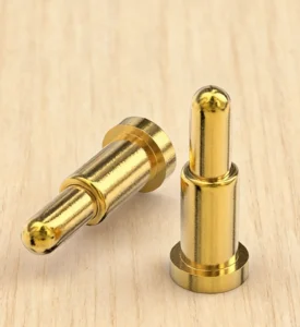
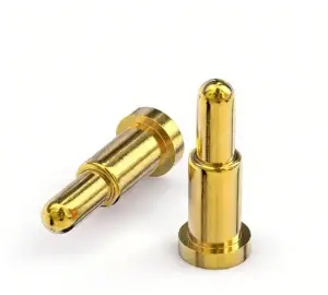
A pogo pin should not be approved as a Mill-Max alternative only because its overall length and barrel diameter appear similar. A qualified second source must be compared by exact part number, drawing revision, working stroke, spring force, contact geometry, electrical limits, material stack, PCB interface, assembly process and application-level validation.
Qualifying an alternative to a Mill-Max spring-loaded contact is an engineering change, not a simple purchasing substitution. A candidate pogo pin may look dimensionally similar while behaving differently after it is installed in the PCB, compressed to the device working height or exposed to the actual electrical and mechanical load.
The objective is not to find the lowest-priced component that fits into the same hole. The objective is to confirm that the candidate contact satisfies the product requirements without creating new PCB, assembly, thermal, electrical or reliability risks.
This guide explains how engineers and procurement teams can evaluate a Mill-Max pogo pin alternative, establish a controlled cross-reference and qualify a second source before updating the bill of materials.
Mill-Max is a trademark of its respective owner. References in this article are used only to identify original components for engineering comparison. CTP is not affiliated with or endorsed by Mill-Max.
What Does “Mill-Max Pogo Pin Alternative” Mean?
The phrase can refer to several different levels of equivalence.
| Equivalence Level | What Has Been Confirmed | What Has Not Necessarily Been Confirmed |
|---|---|---|
| Similar product | General product type and appearance | Dimensions, force, materials and performance |
| Dimensional alternative | Selected external dimensions | Working behavior and assembly compatibility |
| Form-and-fit alternative | Mechanical installation and mating geometry | Electrical and long-term functional performance |
| Form-fit-function alternative | Installation, operation and defined functional requirements | Customer approval and production-process equivalence |
| Approved second source | Product, process, documentation and application validation | Future uncontrolled material or process changes |
| Drop-in replacement | All approved requirements can be met without product or process changes | Nothing outside the agreed qualification scope |
The term drop-in replacement should be used only after the candidate has passed the agreed qualification. It should not be used as the starting assumption.
Why Matching the Overall Dimensions Is Not Enough
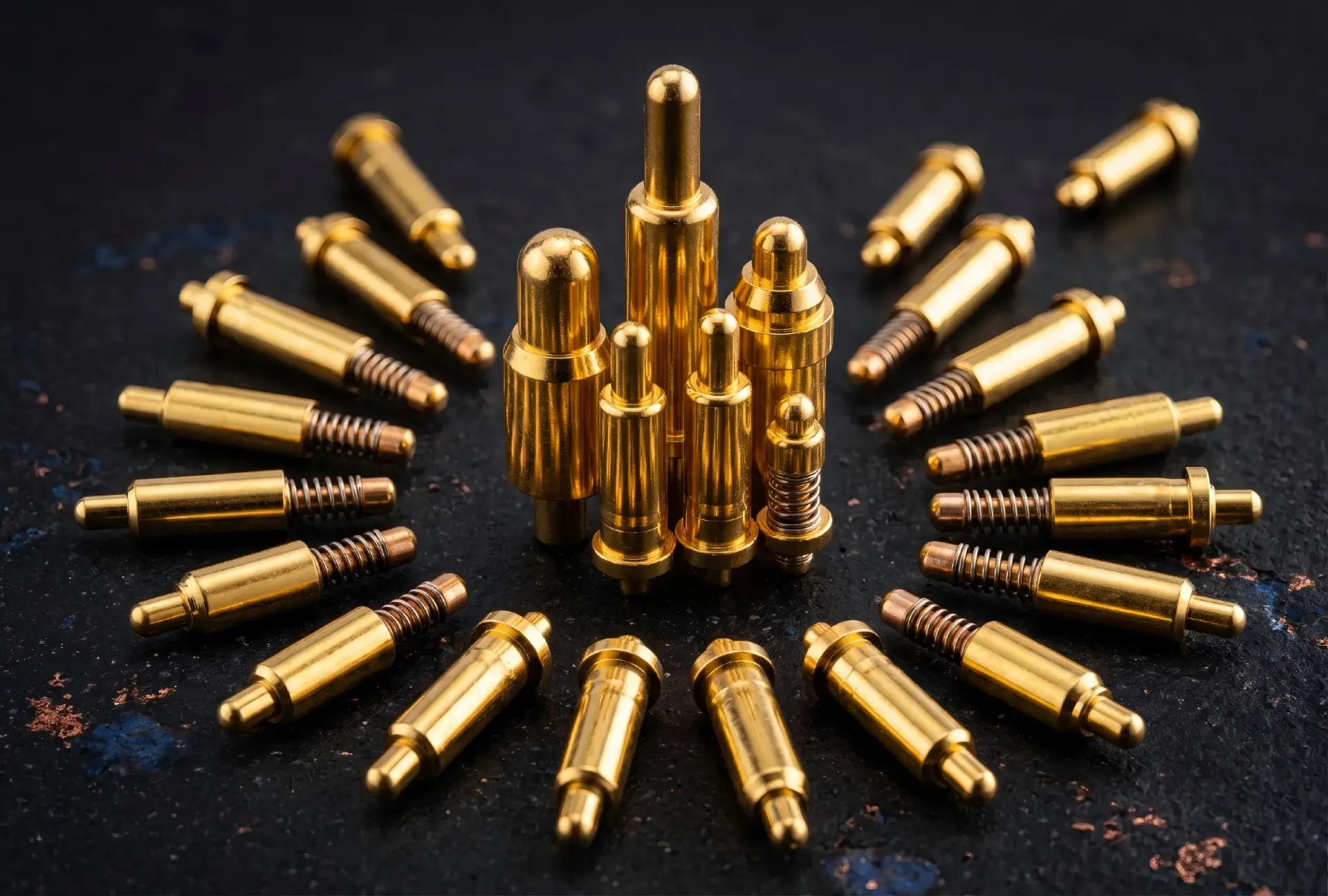
A spring-loaded pin contains several interacting features:
- Plunger and contact tip
- Barrel or shell
- Internal spring
- Rear termination
- Mounting shoulder or barb
- Plating and underplate
- Internal current path
Two contacts with the same total height may have different:
- Free plunger height
- Total travel
- Recommended working stroke
- Force at the installed height
- Available over-travel
- Tip diameter or radius
- Barrel seating position
- Tail dimensions
- PCB installation depth
These differences can change contact force, mating-pad wear, current sharing, PCB loading and final device alignment.
Step 1: Identify the Exact Original Part
Begin with the complete original manufacturer part number rather than only a product family such as “0850 series” or “surface-mount pogo pin.”
Collect:
- Complete part number
- Official product drawing
- Drawing revision or download date
- Selected spring option
- Selected plating option
- Packaging option
- PCB footprint
- Assembly instructions
- Current approved supplier
- Customer-specific requirements
Do not rely only on a distributor description. Distributor listings can omit spring, plating, packaging or lifecycle information contained in the manufacturer documentation.
Confirm How the Original Contact Is Used
The same pogo pin may perform differently in different products.
Document the actual application:
- Power, ground, signal or detection function
- Operating voltage
- Continuous and peak current
- Installed working height
- Mating target material and finish
- Expected mating frequency
- PCB mounting method
- Housing and enclosure support
- Vibration and cable loading
- Operating temperature
- Humidity, contamination or chemical exposure
A second source should be qualified against the actual device requirement, not only against a catalog table.
Step 2: Build a Controlled Cross-Reference Matrix
A useful cross-reference compares requirements line by line.
| Characteristic | Original Contact | Candidate Contact | Acceptance Status |
|---|---|---|---|
| Overall free height | Official drawing value | Candidate drawing value | Match, acceptable deviation or redesign required |
| Recommended working height | Approved device condition | Candidate operating window | Within range or outside range |
| Total travel | Original drawing | Candidate drawing | Over-travel margin confirmed or not confirmed |
| Spring force | Force at defined stroke | Force at the same installed stroke | Meets device force budget or requires review |
| Contact-tip geometry | Original shape and dimensions | Candidate shape and dimensions | Mating-pad compatibility confirmed or not confirmed |
| Barrel and tail dimensions | Original drawing | Candidate drawing | PCB and housing compatibility |
| Contact resistance | Specified test condition | Same measurement condition | Equivalent, improved or insufficient |
| Current and temperature rise | Original condition | Candidate test condition | Comparable or not directly comparable |
| Materials and plating | Original approved stack | Candidate proposed stack | Equivalent or requires validation |
| Assembly compatibility | Existing production process | Candidate process limits | No change or process change required |
Any field marked “unknown” should remain an open qualification item. It should not be recorded as equivalent based on appearance or supplier statements alone.
Step 3: Compare Every Critical Dimension
Overall Height and Installed Height
Compare:
- Free height
- Barrel height
- Plunger projection
- PCB seating height
- Shoulder position
- Installed working height
A small height difference can change the spring force applied to the mating pad.
Barrel Diameter and Mounting Feature
For press-fit or through-hole contacts, confirm:
- Minimum and maximum barrel diameter
- Barb or knurl geometry
- Recommended finished hole
- Plated or non-plated hole requirement
- PCB or insulator thickness
- Required insertion depth
- Insertion and retention force
An alternative should not be pressed into the original hole until the complete fit relationship has been reviewed.
SMT Footprint
For surface-mount contacts, compare:
- Base diameter
- Solderable surface area
- Recommended land pattern
- Solder-mask opening
- Paste-mask opening
- Component center of gravity
- Pick-up surface
- Package orientation
A contact that physically sits on the original pad may still require a different stencil aperture or reflow evaluation.
Tail and Termination Geometry
Confirm whether the part uses:
- Surface-mount base
- Through-hole solder tail
- Press-fit feature
- Solder cup
- Right-angle tail
- Crimp, weld or custom termination
The term “DIP pogo pin” is too general for a controlled cross-reference.
Step 4: Compare the Working Stroke and Spring Force
Spring force must be compared at the actual device working stroke.
Do not compare:
- The original force at mid-stroke with the candidate force at another stroke
- Typical force with a maximum-force requirement
- One spring option with a different spring option
- Grams-force and newtons without conversion
The force review should include:
| Condition | Required Comparison |
|---|---|
| Minimum installed compression | Minimum contact force and electrical stability |
| Nominal installed compression | Normal force, resistance and device load |
| Maximum installed compression | Maximum force, over-travel and structural loading |
| Post-cycling condition | Force retention and return height where required |
A candidate with a different spring rate may match the original at one point but differ significantly at the minimum or maximum assembly condition.
Total Connector Force Must Also Be Reviewed
When several pogo pins are installed together, their forces accumulate.
A small difference per pin can become significant in a multi-pin connector:
Total spring load = sum of the force from every compressed contact
The review should include:
- PCB deflection
- Housing load
- Magnetic holding margin
- User mating force
- Mating-pad pressure
- Parallel-contact compression consistency
Step 5: Compare the Contact-Tip Geometry
The tip shape influences the contact interface.
Compare:
- Flat tip
- Rounded tip
- Conical tip
- Crown or serrated tip
- Ball or rolling-contact structure
- Custom tip diameter and radius
A different tip can change:
- Contact area
- Local pressure
- Ability to move through surface films
- Pad indentation
- Plating wear
- Sliding behavior
- Debris generation
A candidate should be evaluated with the actual production mating pad rather than only a laboratory metal plate.
Step 6: Compare Electrical Performance Under the Same Conditions
Contact Resistance
A resistance value is meaningful only when the measurement boundary and test condition are defined.
Confirm:
- Whether the value applies to the internal pogo pin or complete mated interface
- Measurement points
- Test current
- Working stroke
- Mating target
- Sample temperature
- Initial or post-conditioning state
IEC 60512-2-2 provides a standardized method for measuring resistance across mated contacts using a specified test current, but the product specification must still define the measurement points and acceptance limit.
Current Capability
Do not compare current ratings unless the temperature-rise and installation conditions are comparable.
Current performance also depends on:
- Internal contact structure
- Spring and barrel current path
- Working stroke
- PCB copper
- Wire size
- Ambient temperature
- Enclosure heat dissipation
- Duty cycle
The candidate should be evaluated in the final electrical path when the pogo pin carries meaningful power.
Parallel Power Contacts
When several pogo pins are connected in parallel, measure each path where practical.
Differences in force, resistance, PCB routing and pad alignment can cause unequal current sharing. A combined current measurement can hide one overloaded contact.
Step 7: Review Materials and Plating
Do not assume that every Mill-Max product or every alternative uses one universal material combination.
Request component-level information for:
- Plunger material
- Barrel material
- Spring material
- Underplate
- Final contact finish
- Termination finish
- Plated surfaces
The phrase “gold-plated beryllium copper” is not a complete product specification.
The qualification should determine whether differences in materials or finish affect:
- Contact resistance
- Wear
- Spring force
- Solderability
- Corrosion behavior
- Assembly temperature
- Regulatory documentation
Equivalent Performance Does Not Require Identical Materials
A candidate may use a different controlled material system and still satisfy the application requirements.
Material identity and functional equivalence are related but not identical.
There are two possible qualification strategies:
- Design-equivalent approach: Require the candidate to match the original material and plating stack.
- Performance-equivalent approach: Allow a different controlled construction that passes the approved functional and environmental requirements.
The selected approach should be agreed before samples are produced.
Step 8: Verify PCB and Assembly Compatibility
Surface-Mount Contacts
Confirm:
- Packaging and feeder compatibility
- Pick-and-place nozzle access
- Placement accuracy
- Stencil design
- Reflow profile
- Component movement during reflow
- Post-reflow height
- Post-reflow spring return
Through-Hole Contacts
Confirm:
- Finished-hole diameter
- Soldering method
- Hole fill or fillet requirement
- Thermal exposure
- Flux and cleaning process
- Inspection access
Press-Fit Contacts
Confirm:
- PCB or insulator hole
- Insertion tooling
- Insertion depth
- Insertion force
- Retention force
- Substrate damage
- Replacement and rework method
Solder-Cup Contacts
Confirm:
- Wire gauge
- Stripping length
- Soldering temperature and dwell time
- Flux control
- Wire strain relief
- Protection against solder entering the moving barrel
The existing production process should not be described as unchanged until a representative assembly trial has been completed.
Step 9: Design the Sample Qualification Plan
Do not begin by requesting an arbitrary quantity of five Sample Evaluation.
The required sample quantity depends on:
- Number of qualification tests
- Destructive and non-destructive tests
- Number of production lots represented
- Number of PCB assemblies required
- Customer approval requirements
- Application risk
A practical sample plan may separate specimens into groups:
| Sample Group | Purpose |
|---|---|
| Dimensional samples | Drawing and PCB compatibility |
| Force samples | Force-stroke measurement and return behavior |
| Electrical samples | Resistance, voltage drop and temperature rise |
| Assembly samples | SMT, through-hole, press-fit or wire-process trial |
| Mechanical-operation samples | Project-defined mating cycles and wear evaluation |
| Environmental samples | Temperature, humidity, vibration or chemical conditioning |
| Device-level samples | Final PCB, housing and mating-target validation |
Step 10: Perform Side-by-Side A/B Testing
Where practical, test the original and candidate contacts using the same:
- PCB
- Housing
- Mating target
- Working height
- Electrical load
- Test fixture
- Environmental condition
- Measurement method
Record individual sample results rather than only pass/fail summaries.
Useful comparison outputs include:
- Force-displacement curves
- Contact resistance distribution
- Voltage-drop distribution
- Temperature-rise curves
- Installed-height measurements
- Wear photographs
- Post-cycling force and resistance
Step 11: Validate the Finished Device
Component-level equivalence does not automatically prove device-level equivalence.
Final validation should include the relevant:
- Production PCB
- Production mating pad
- Connector housing
- Mechanical stop
- Device enclosure
- Cable or dock
- Electrical load
- Firmware or detection logic
Possible device-level checks include:
- Charging stability
- Device reset behavior
- Detection-signal stability
- PCB deflection
- Housing fit
- Mating-pad wear
- Vibration continuity
- Thermal performance
Step 12: Run a Representative Pilot Lot
The first samples may be selected or assembled manually by engineering staff. A pilot lot should demonstrate that the candidate can be produced consistently using the intended:
- Materials
- Tooling
- Production equipment
- Packaging
- Assembly process
- Inspection methods
The pilot review should measure:
- Dimensional variation
- Spring-force variation
- Contact-resistance variation
- PCB assembly yield
- Defect categories
- Handling and packaging damage
- Traceability records
A second source should not be released solely on the basis of individually selected engineering samples.
Step 13: Establish Supplier Change Control
The approved alternative applies to a controlled product and process state.
Changes requiring review may include:
- Plunger material
- Barrel material
- Spring material or force
- Plating stack or plating supplier
- Tip geometry
- Manufacturing tooling
- Assembly equipment
- Production location
- Packaging format
- Inspection method
The supply agreement should define notification, approval and revalidation requirements.
Cost Optimization Should Use Total Cost, Not Unit Price Alone
The purchase price of the contact is only one part of the sourcing decision.
Calculate the total cost of ownership using:
- Unit price
- Minimum order quantity
- Tooling or NRE charges
- Sample and qualification costs
- Freight and import costs
- Inventory carrying cost
- Lead-time buffer stock
- Production-line changes
- Inspection requirements
- Yield and rework
- Supplier management cost
- Potential field-failure exposure
A lower unit price may not create a lower total cost when it requires PCB changes, additional inspection or higher safety inventory.
Do Not Promise a Universal 30–40% Cost Reduction
Cost savings depend on:
- Part construction
- Annual quantity
- Plating requirement
- Spring option
- Packaging
- Documentation
- Testing
- Commercial terms
A responsible supplier should provide a project-specific quotation after the original part, annual volume and qualification requirements are confirmed.
Lead Time Must Also Be Verified by Project
Do not state that one brand always requires four to eight weeks or that an alternative is always faster.
Lead time can change with:
- Stock status
- Plating option
- Spring option
- Packaging
- Custom tooling
- Order quantity
- Production loading
Compare quoted lead time, sample lead time and repeat-order lead time separately.
When Is a Magnetic Connector an Upgrade Rather Than a Replacement?
Changing from an individual Mill-Max-style pogo pin to a magnetic pogo pin connector is normally a product redesign, not a drop-in substitution.
A magnetic interface may be considered when the product requires:
- Magnet-assisted docking
- A detachable charging cable
- One-handed placement
- A controlled breakaway point
- A custom external interface
- A removable module
The redesign may require changes to:
- PCB layout
- Pin Map
- Mating targets
- Device enclosure
- Mechanical stops
- Magnets and retention structure
- Charging or detection circuitry
- Cable assembly
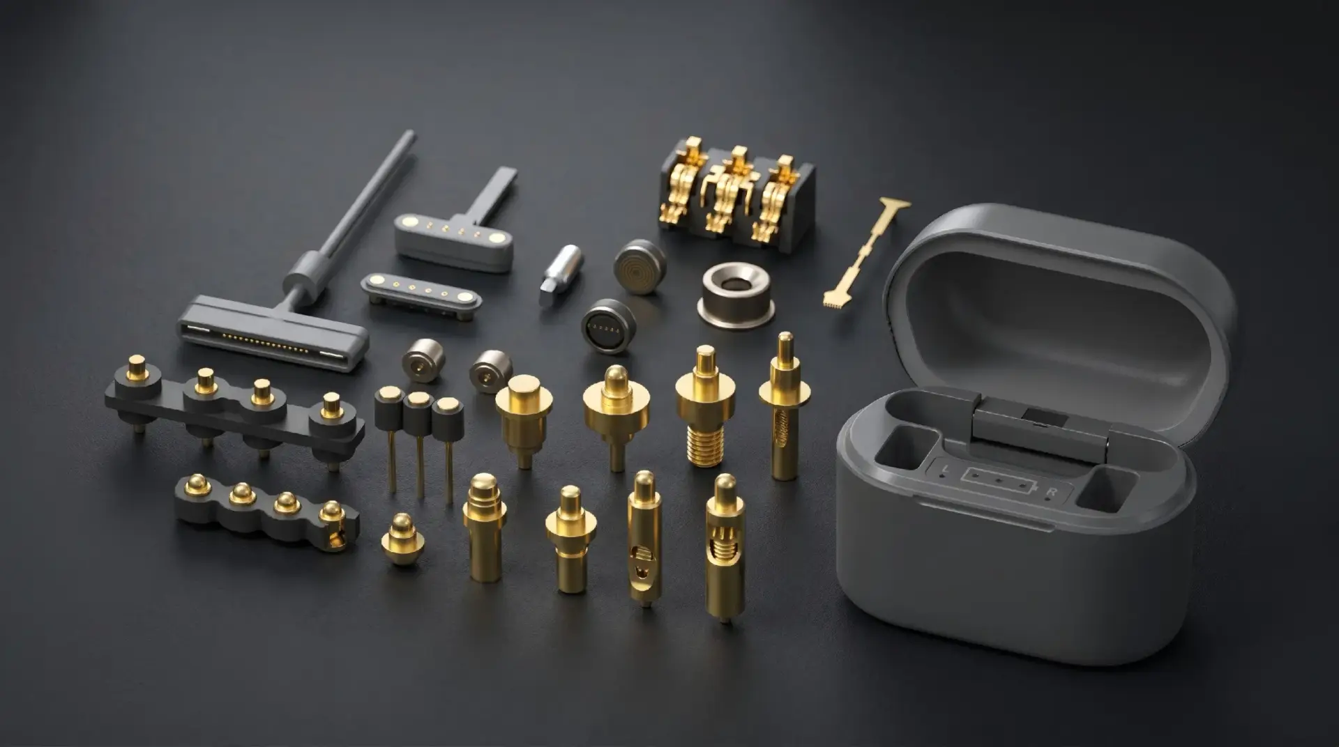
Magnet grade, IP rating, holding force and electrical capability should be selected and validated for the specific connector. They should not be inferred from a product photograph or generic magnetic-connector description.
Information to Send for a Cross-Reference Review
Prepare:
- Complete original manufacturer part number
- Original drawing and datasheet
- Current annual and order quantities
- PCB footprint or Gerber information
- Housing and STEP files
- Installed working height
- Mating-target drawing and finish
- Voltage and current
- Signal function
- Expected mating frequency
- Operating environment
- Assembly process
- Packaging requirement
- Required regulatory documents
- Required qualification tests
A part number alone is sufficient for an initial search, but it is not sufficient for final approval.
Recommended Qualification Matrix
| Qualification Area | Minimum Review | Possible Evidence |
|---|---|---|
| Product identity | Part number, revision and configuration | Controlled drawing and BOM |
| Dimensions | All installation and mating dimensions | Dimensional inspection report |
| Force and stroke | Minimum, nominal and maximum working conditions | Force-displacement data |
| Electrical | Resistance, voltage drop and temperature rise | Test report with defined measurement boundaries |
| Materials | Plunger, barrel, spring and plating | Drawing, declaration or certificate |
| PCB assembly | Footprint and production-process compatibility | Assembly trial and inspection |
| Repeated operation | Project-specific cycle requirement | Pre-test and post-test force, resistance and wear |
| Environment | Application-specific exposure | Conditioning and post-test inspection |
| Production readiness | Normal production variation | Pilot-lot data and control plan |
| Change control | Future change-notification rules | Quality agreement |
Common Pogo Pin Replacement Mistakes
| Mistake | Possible Consequence | Better Approach |
|---|---|---|
| Comparing only overall length and diameter | Working stroke or PCB position may change | Compare the complete controlled drawing |
| Calling a candidate a drop-in replacement before testing | Customers may assume approval that has not occurred | Use “candidate cross-reference” until qualification is complete |
| Copying current and resistance values without test conditions | The specifications may not be directly comparable | Use the same measurement path and operating condition |
| Assuming all pogo pins use the same materials | Material or process differences remain hidden | Request component-level material and plating information |
| Testing only with a multimeter | Force, temperature rise and dynamic instability are missed | Use dimensional, mechanical, electrical and device-level testing |
| Assuming the existing reflow process is unchanged | Component tilt, solder defects or spring damage may occur | Run a production-intent assembly trial |
| Promising fixed cost savings | Qualification and process costs may eliminate the saving | Calculate project-specific total cost of ownership |
| Promising samples promised before engineering review for every part | Custom tooling or plating may require more time | Quote sample timing after configuration review |
| Calling a magnetic connector a direct upgrade | Required PCB and enclosure redesign is hidden | Treat magnetic integration as a separate architecture project |
| Approving one selected sample | Normal production variation remains unknown | Review representative samples and a pilot lot |
Frequently Asked Questions
Can CTP provide a direct replacement for every Mill-Max pogo pin?
No supplier should assume that every part has an immediate direct replacement. CTP can review the original part number and application, identify a candidate construction and determine what must be validated before approval.
What information is needed to cross-reference a Mill-Max part?
Provide the complete part number, official drawing, installed working height, PCB footprint, mating target, electrical load, assembly process and environmental requirements.
Is matching the outer dimensions enough?
No. Spring force, working stroke, tip geometry, internal construction, materials, plating and assembly behavior can still differ.
What is the difference between a cross-reference and a drop-in replacement?
A cross-reference is a candidate selected for comparison. A drop-in replacement is a qualified component that meets the approved form, fit, function and production requirements without requiring unintended changes.
Must the alternative use exactly the same materials?
Not necessarily. The customer may require design-equivalent materials, or it may permit a different controlled construction that passes the approved performance requirements.
Can contact resistance be checked with a normal multimeter?
A multimeter may support basic continuity screening, but low-resistance qualification usually requires controlled measurement points, working stroke and a suitable low-resistance method.
Will a second-source pogo pin use the same PCB footprint?
It may, but the terminal dimensions, recommended land pattern, hole requirement, stencil and installed height must be compared before the PCB process is approved.
How many samples are needed?
The quantity depends on the required dimensional, force, electrical, assembly, life and environmental tests. Samples should be allocated by test group rather than chosen from a universal quantity.
Can changing suppliers reduce pogo pin costs?
It may reduce unit or total sourcing cost, but the result depends on volume, specifications, tooling, qualification, logistics, inventory, assembly yield and commercial terms.
Is converting to a magnetic pogo pin connector a direct replacement?
Usually not. Adding magnets normally changes the PCB, mating target, housing, force system and user interface, so it should be treated as a new connector architecture.
Prepare a Pogo Pin Second-Source Review
Begin by freezing the exact original contact and documenting how it operates inside the finished device.
Review available individual pogo pin structures, compare multi-pin pogo pin connector assemblies, explore custom magnetic connector architectures, or access additional engineering guides.
Submit the original part number, datasheet, working height, PCB drawing and application requirements through the Get Quote & Samples page.
CTP can prepare a candidate cross-reference matrix covering dimensions, working stroke, force, electrical requirements, material stack and PCB integration. Final equivalence and production approval should be based on the customer’s completed qualification and approved project documents.