
01
Pin Map and Contact FunctionsDefine the function of each power, return, signal, control or detection contact.
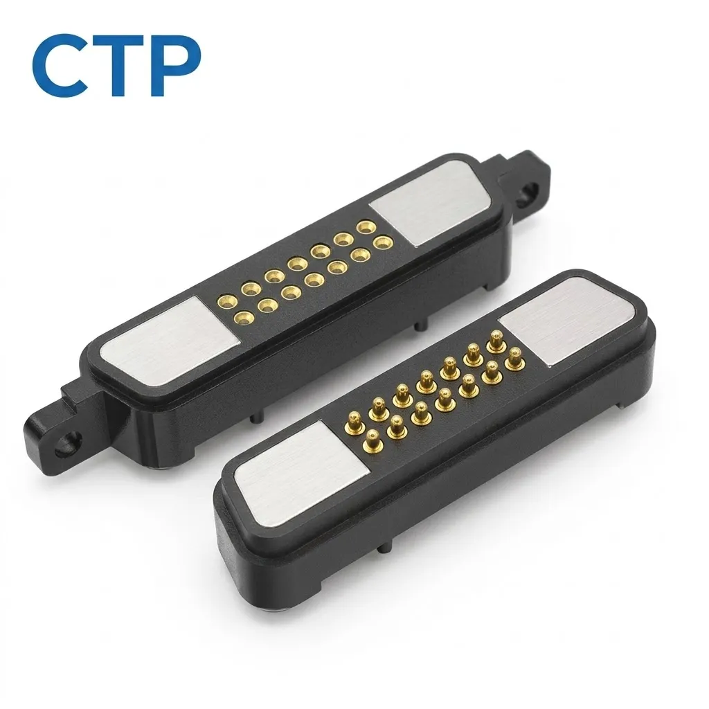
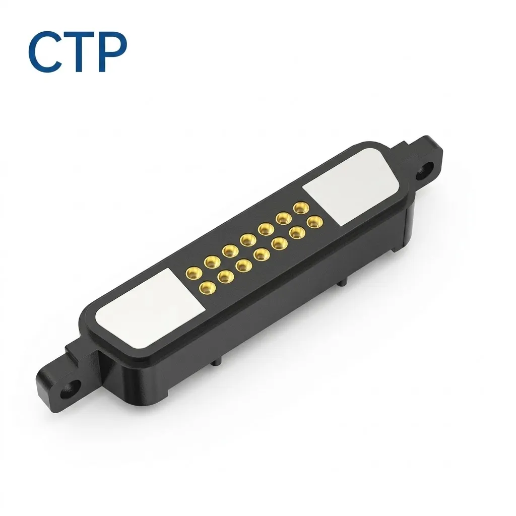
| SKU / inquiry reference | CTP-MPC-14P-DR-A01 |
|---|---|
| Contact count / series | 14 |
| Contact layout | Dual row |
These are the pictured configuration and existing catalog references, not newly measured test results. Customer-specific dimensions, electrical ratings, sealing and reliability targets remain subject to the approved drawing and validation conditions.
SKU: CTP-MPC-14P-DR-A01
Values shown describe this product configuration. Customized dimensions, electrical ratings, materials and acceptance criteria are subject to the customer-approved drawing and agreed specification.
Request a drawing for SKU CTP-MPC-14P-DR-A01
Browse the reference drawing library — library drawings are reference structures, not approved drawings for this SKU.
14-pin dual-row magnetic pogo pin connector with a 7 × 2 contact arrangement, a 10 A current rating and 36 V rated voltage. The specified protection rating is IP54. Gold-plated copper contacts and a brass housing support the mating connector interface. Custom dimensions, pin assignments and integration details are confirmed in the approved project drawing.
Product specifications should be reviewed together with the customer device, PCB, electrical assignment and mechanical mating conditions.
Define the function of each power, return, signal, control or detection contact.
Provide voltage, continuous current, peak current and required signal conditions.
Provide available length, width, height, PCB area and required mating orientation.
Provide application, expected quantity, environment and customer validation requirements.
Review the product-specific description, technical parameters, contact arrangement, mechanical structure and project conditions below.
This 14-pin dual-row magnetic pogo pin connector uses a compact 7 × 2 contact arrangement. The specified current rating is 10 A, the rated voltage is 36 V, and the specified ingress-protection rating is IP54. Gold-plated copper contacts and a brass housing form the electrical and mechanical interface. The product is shown as a mating connector pair, with a spring-contact half and a corresponding flat-contact half.
Magnetic elements positioned near both ends assist capture and retention during mating. Final connector seating and alignment should be controlled by the approved mechanical interface, while the spring-loaded contacts provide electrical connection and controlled Z-axis compliance.
Fourteen contact positions are arranged as seven contacts per row across two parallel rows. Compared with a long single-row contact array, this dual-row architecture can support a more compact contact field where the available connector length is constrained.
The fourteen contacts provide available interface positions only. Their electrical functions must be assigned through the customer-approved pin map.
The visible product configuration includes a spring-contact half and a corresponding mating contact half. The final mounting structure, termination method and male/female naming convention should follow the approved project drawing.
The connector performs three separate functions during mating:
Magnetic capture does not by itself confirm complete mechanical seating or a valid electrical connection.
A 14-pin interface provides multiple contact positions, but pin count does not determine their function. Power, return, control, detection and signal assignments should be established according to the electrical architecture of the customer device.
The approved pin map should identify each contact function and any required ground or return paths before the connector interface is released for production.
The specified current rating for this model is 10 A. Evaluate the intended application across the complete conductive path:
Source → PCB / cable → termination → pogo pin → contact interface → target → load.
Use the specified 10 A model rating when reviewing the application. Fourteen contact positions do not imply fourteen times this rating. Where contacts are assigned in parallel, current sharing and thermal conditions should be evaluated for the approved circuit.
Voltage drop and power loss should be considered using the resistance of the complete interface rather than the pogo pin alone.
Fourteen contacts provide flexibility for defining multiple interface functions, but the number of contacts does not establish data bandwidth.
Data capability should be reviewed using the actual pin map, return-path strategy, contact pitch, contact geometry, PCB transition, FPC or cable structure and the complete communication channel.
The connector uses a brass housing with gold-plated copper contacts. Integrate the connector with the device housing, PCB position and mating geometry. Final mechanical positioning should be established by defined datums, guidance features or stops rather than magnetic attraction or pogo-pin compression alone.
If the project requires protection against reverse orientation or incorrect mating, the connector geometry should include a defined polarization or keying strategy. The effectiveness of that strategy must be reviewed from the complete mating geometry rather than inferred from magnetic attraction alone.
Anti-mismating capability for this specific configuration should be confirmed from the approved mechanical drawing before it is specified as a product feature.
The spring-loaded contacts should operate within the working stroke specified on the approved connector drawing. Working stroke must be distinguished from total mechanical travel.
The pogo pins should provide controlled contact compliance and should not be used as the structural stop for the connector assembly.
Magnetic elements at the ends of the connector assist mating capture and retention. The required magnetic behavior should be defined according to the application rather than simply selecting the highest available magnetic force.
Capture force, retention force, separation force and peel force can represent different requirements and should be evaluated independently when relevant.
| Parameter | Specification |
|---|---|
| Product reference / SKU | CTP-MPC-14P-DR-A01 |
| Product type | Magnetic Pogo Pin Connector |
| Configuration | Mating connector pair |
| Contact count | 14 |
| Contact layout | 7 × 2 |
| Row configuration | Dual row |
| Housing shape | Elongated rectangular |
| Contact interface | Spring-contact half + flat-contact half |
| Rated current | 10 A |
| Rated voltage | 36 V |
| IP rating | IP54 |
| Contact material | Gold-plated copper |
| Housing material | Brass |
Dimensions, contact pitch, row spacing, working stroke, pin assignment, mounting and termination are confirmed in the approved drawing for the ordered configuration. Customer-specific values remain subject to the approved project drawing.
Application areas for evaluation include aerospace equipment, audio/video interfaces, automotive equipment, data communication, electrical equipment, FPC integration, LED lighting, microwave equipment, PCB interconnects, power interfaces and RF interfaces. The 7 × 2 dual-row contact field provides fourteen positions for the approved application circuit.
Confirm application suitability using the pin assignment, 10 A current rating, 36 V rated voltage, IP54 specification, installation space and completed device architecture. Microwave and RF applications require review of the actual frequency, impedance, contact geometry and complete signal path. Application categories do not establish a universal frequency range or data rate.
This model has a specified IP54 ingress-protection rating. Confirm the mating condition and installation arrangement for the ordered configuration. The connector interface, brass housing, mounting structure and completed enclosure should be reviewed together for the intended environment.
The contact material is gold-plated copper and the housing material is brass. Any additional salt-spray requirement, gold-plating thickness, operating-temperature range or environmental test requirement should be confirmed for the ordered configuration.
CTP can review project-specific requirements including connector dimensions, contact spacing, pin assignment, termination structure, mounting geometry, mating architecture and magnetic behavior.
Final dimensions and electrical specifications should be released through an approved 2D drawing and, where required, a 3D model.
The connector uses a dual-row 7 × 2 contact arrangement, providing fourteen independently assignable contact positions.
No. Pin count does not determine data bandwidth. Data capability depends on the pin map, return paths, contact geometry, PCB transitions and the complete communication channel.
This model is specified at 10 A. Changing pin allocation does not establish a higher rating. Any parallel-contact design should be reviewed for current sharing, termination resistance and thermal performance across the complete conductive path.
The specified current rating is 10 A and the rated voltage is 36 V. Review the contact assignments, conductors, termination and mating interface for the intended application.
Anti-mismating or polarization performance should only be specified when the mechanical keying strategy has been confirmed by the approved connector and device drawings.
The magnets assist capture and retention. Final alignment and seating should be controlled by the mechanical features of the completed mating interface.
The specified ingress-protection rating for this model is IP54. Confirm the applicable mating and installation conditions for the ordered connector and the completed device assembly.
Provide the available installation space, pin map, voltage, continuous and peak current, signal requirements, working stroke, mating tolerance, magnetic requirements, termination method and available 2D or 3D drawings.
If this 14-pin dual-row magnetic connector architecture is close to your device requirements, submit the pin map, electrical conditions, available installation space and mating requirements for engineering review.
Request Custom Quote & Samples | Browse Magnetic Connectors
The model specifications are listed in the Product Specifications table above. The specified ratings are 10 A, 36 V and IP54, with gold-plated copper contacts and a brass housing. Custom changes to dimensions, pin assignment, ratings, materials or sealing are confirmed against the approved project drawing and application requirements.
CTP reviews the application and prepares a drawing or specification for approval before sample production. Test scope, acceptance criteria and report format should identify the model, sample status, method, conditions, result and review date.
Yes. Customization can cover geometry, contact layout, materials, cable construction, magnetic structure, sealing and appearance. Feasibility depends on the application and approved specification.
No. Current, voltage, resistance, temperature rise and ingress-protection claims apply only to the identified model and stated test conditions.
Timing is confirmed after the drawing, materials, tooling, sample quantity, validation scope and production requirements have been reviewed.
Submit your Pin Map, electrical requirements, available space, mating structure and project quantity for connector selection or custom development review.

Use the following engineering guides to compare contact count, contact allocation and connector layout before confirming the final product or customized design.
Review the complete selection path from contact count and electrical functions to connector shape.
View Main Guide →Compare one-contact special structures, complete two-contact circuits and third-contact functions.
Compare Low-Pin Designs →Determine whether four contacts are sufficient or whether a defined fifth electrical path is required.
Compare 4 Pin and 5 Pin →Calculate the contact budget and compare six-contact, multi-row and customized contact-array structures.
Compare High-Pin Designs →