Engineering Summary:
Pogo pin charging solutions can support automated conductive charging
interfaces for new energy vehicles (NEVs), especially in controlled
fleet depots, robotic docking stations, battery-swap equipment and other
applications where repeatable unattended mating is required. Spring-loaded
contacts can accommodate a defined amount of Z-axis variation, but they do
not replace vehicle positioning, mechanical guidance, power sequencing or
electrical safety controls. A reliable EV charging interface should treat
docking, contact compression, connection detection and power enable as
separate engineering states.
Pogo pin charging solutions can support automated conductive charging
interfaces for new energy vehicles (NEVs), especially in controlled
fleet depots, robotic docking stations, battery-swap equipment and other
applications where repeatable unattended mating is required. Spring-loaded
contacts can accommodate a defined amount of Z-axis variation, but they do
not replace vehicle positioning, mechanical guidance, power sequencing or
electrical safety controls. A reliable EV charging interface should treat
docking, contact compression, connection detection and power enable as
separate engineering states.
What Is a Pogo Pin EV Charging Solution?
A pogo pin EV charging solution is a conductive electrical interface that
uses spring-loaded contacts to connect a charging system with a vehicle,
battery module or another removable electrical assembly.
Unlike wireless charging, electrical current crosses the interface through
direct metal-to-metal contact.
A complete automated charging system may contain:- vehicle or battery positioning hardware;
- mechanical guide features;
- spring-loaded pogo pin contacts;
- flat or shaped mating targets;
- connection-detection contacts or sensors;
- power switching and interlock electronics;
- charging-control electronics;
- environmental protection and drainage structures.
The pogo pins are therefore one part of the charging architecture rather
than the complete charging system.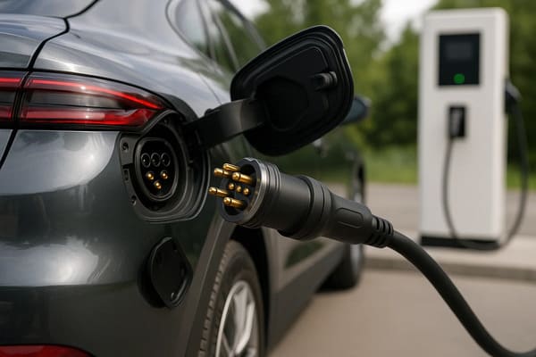
battery docking system. Final electrical ratings and charging behavior
depend on the complete system design.
Where Can Pogo Pin Charging Fit in New Energy Vehicles?
New energy vehicle charging includes several different interface types.
A pogo pin architecture is not equally suitable for all of them.| NEV Interface | Possible Pogo Pin Role | Primary Engineering Focus |
|---|---|---|
| Automated Fleet Dock | Unattended conductive charging | Positioning, repeated docking and power sequencing |
| Battery-Swap Equipment | Repeated removable battery connection | Alignment, current path, interlock and lifecycle |
| Autonomous Shuttle / Robot Vehicle | Dedicated charging station interface | Docking tolerance and connection detection |
| Commercial Fleet Depot | Project-specific automatic charging | Availability, contamination and maintenance |
| Auxiliary Vehicle Electronics | Low-voltage charging or service interface | Voltage drop, accessibility and serviceability |
| Public Traction Charging | Requires additional system-level evaluation | Standardization, insulation, locking, communication and certification |
Pogo pin charging is therefore especially relevant when the vehicle,
charging station and mating sequence are controlled as one system.
How Does a Pogo Pin Charging Contact Work?
A spring-loaded contact typically contains a plunger, spring and barrel or
body structure.

When the vehicle or battery reaches the charging position, the mating
target compresses the plunger.

The internal spring provides contact force while allowing controlled
movement along the contact axis.| Component | Engineering Function |
|---|---|
| Plunger | Creates the movable electrical contact with the mating target |
| Spring | Provides contact force through a defined compression range |
| Barrel / Body | Guides plunger motion and supports the internal contact structure |
| Termination | Connects the pogo pin to a wire, PCB, busbar or another conductor |
| Mating Target | Provides the vehicle- or battery-side contact surface |
Exact materials, plating, spring force and electrical ratings should be
defined by the approved contact design rather than assumed from a generic
pogo pin architecture.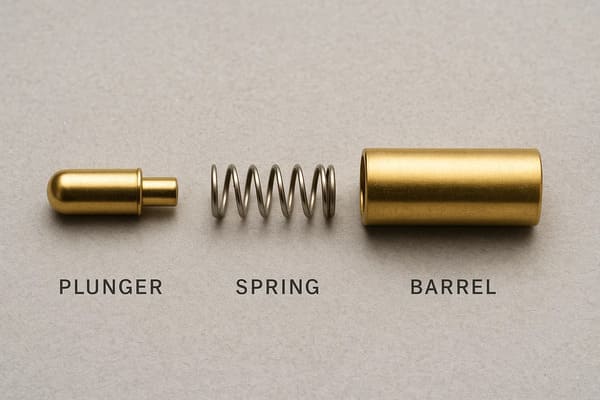
current capability depend on the selected pogo pin design.
Pogo Pins Provide Compliance — Not Vehicle Alignment
One of the useful characteristics of a pogo pin is its ability to absorb a
controlled amount of variation along the Z-axis.

However, this should not be confused with automatic vehicle alignment.

A pogo pin should not be expected to correct large lateral or angular
docking errors.
A controlled automatic charging system may use:
- vehicle-position detection;
- mechanical guide rails;
- tapered locating surfaces;
- guide pins;
- floating connector mounts;
- compliant charging heads;
- robotic positioning;
- final pogo pin spring compliance.
The larger positioning error should be removed by the charging mechanism
before the pogo pins reach their final electrical condition.
The Charging System Should Establish Mechanical Position First
The preferred design principle is:


    Mechanical structure defines the vehicle or battery position; pogo
    pins provide the electrical connection.
| Docking Function | Recommended Control |
|---|---|
| Vehicle Approach | Vehicle guidance or robotic positioning |
| Coarse Alignment | Mechanical guides |
| Final Position | Mechanical datum and stop |
| Electrical Compliance | Pogo pin working stroke |
| Connection Detection | Sensor, pilot contact or project-specific detection architecture |
| Power Enable | Charging controller and switching system |
Pogo Pins Should Not Carry Vehicle Structural Loads
The spring-loaded contacts should primarily provide electrical contact.

Vehicle mass, battery-module clamping forces and docking impact should be
carried by dedicated mechanical structures.
A preferred load path is:
    Vehicle / Battery Module
    →
    Docking Structure
    →
    Mechanical Stops
    →
    Charging Station
rather than:
    Vehicle
    →
    Pogo Pin Plunger
    →
    Spring
    →
    PCB / Termination


This helps prevent excessive compression, side loading and damage to the
electrical contacts.
Working Stroke Defines the Final Electrical Contact State
Once docking is complete, every power and signal pogo pin should operate
inside its approved working-compression range.
A simplified relationship is:
S = Hfree - Hseatedwhere:
- S is actual pogo pin compression;
- Hfree is the installed free height;
- Hseated is the final contact height after docking.
| Contact Condition | Possible Effect |
|---|---|
| Insufficient Compression | Unstable or higher-resistance contact |
| Approved Working Stroke | Intended contact force and electrical state |
| Excessive Compression | Spring bottoming, target wear or structural overload |
| Unequal Compression | Different resistance across multiple charging contacts |
Total Travel Is Not the Normal Charging Stroke
A pogo pin may physically move farther than its recommended operating
compression.

The vehicle or battery should not use the mechanical bottom of the pogo pin
as the docking stop.

Mechanical stops should control final position while the pogo pins operate
inside their approved working range.
How an Automated Pogo Pin Charging Cycle Can Work
One of the main advantages of a spring-contact architecture is compatibility
with controlled automated mating.
A possible charging sequence is:
    Vehicle Approaches
    →
    Position Confirmed
    →
    Mechanical Docking
    →
    Pogo Pins Compressed
    →
    Connection Detected
    →
    Electrical Validity Check
    →
    Power Enable
    →
    Charging


The exact implementation differs by vehicle and charging architecture, but
this separation of mechanical and electrical states is important.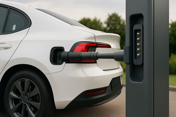
seating and electrical validation should occur before the main charging
path is enabled.
Automatic Docking Does Not Mean Automatic Power Enable
Physical contact should not automatically command the charging system to
apply full electrical power.

The interface may be physically touching while:- one contact has not reached its working stroke;
- the dock is tilted;
- only part of a parallel power array is engaged;
- foreign debris prevents complete seating;
- the wrong battery or vehicle interface is present.
For this reason, the complete charging architecture may require detection,
identification, interlock, pre-charge or another project-specific
validation state before main charging begins.
Partial Mating Is a Real Electrical Fault Condition
| Partial-Mating State | Possible Risk | Design Response |
|---|---|---|
| One Power Contact Touches First | Unexpected current path | Keep main power disabled |
| Only Some Parallel Contacts Engage | Current concentration | Verify complete seating before charging |
| Dock Is Angled | Unequal working stroke | Mechanical alignment verification |
| Debris Prevents Seating | High or unstable resistance | Fault detection and maintenance |
| Vehicle Begins Moving While Energized | Separation under electrical load | Remove current before undocking |
Undocking Should Also Be a Controlled Sequence
A reliable automated charger should define not only how charging starts,
but also how it stops.
A possible sequence is:
    Charging Current Reduced
    →
    Main Power Disabled
    →
    Electrical State Confirmed
    →
    Mechanical Release
    →
    Pogo Contacts Separate
    →
    Vehicle Departs


A detection or pilot contact can provide information about connector state,
but it does not suppress electrical arcing by itself.
What Are the Main Benefits of Pogo Pin Charging for NEVs?
| Potential Benefit | Why It Can Matter | Engineering Condition |
|---|---|---|
| Automated Connection | Supports unattended fleet or robotic charging | Requires controlled vehicle positioning and power sequencing |
| Spring Compliance | Accommodates controlled Z-axis variation | Working stroke must remain inside the approved range |
| Flat Mating Target | Can simplify certain docking geometries | Target finish, flatness and environmental exposure must be controlled |
| Repeated Docking | Suitable for systems requiring frequent removable connection | Lifecycle must be validated under real docking conditions |
| Custom Pin Map | Can combine power, detection and project-specific contacts | Electrical functions must be deliberately assigned and validated |
| Serviceable Contact Interface | Contacts or target structures can be designed as replaceable modules | Maintenance strategy must be included in system design |
Automated Charging Can Reduce Manual Connection Steps
For a controlled vehicle fleet, one practical reason to consider pogo pin
charging is the ability to integrate electrical connection into the
parking or docking sequence.

This can be useful when:- vehicles return repeatedly to the same charging location;
- charging must occur without an operator;
- the charging station and vehicle are designed together;
- high utilization makes charging availability important;
- the interface can be inspected and maintained as part of fleet operations.
The actual labor, availability or operating-cost improvement depends on the
complete fleet workflow and should not be inferred from the connector
alone.
AGV Charging Is a Useful Adjacent Architecture — Not Proof of EV Suitability
Automated guided vehicles, mobile robots and other industrial equipment
have long used various forms of conductive docking contacts because their
routes and charging positions can be tightly controlled.

This provides a useful architectural reference for automatic NEV charging:- fixed docking position;
- repeatable electrical target;
- automatic connection;
- connection-state monitoring;
- scheduled maintenance.
However, an industrial robot charging interface should not automatically be
treated as electrically or mechanically suitable for a road vehicle.

Vehicle voltage, current, environment, safety requirements and applicable
charging architecture must be evaluated separately.
Pogo Pin Charging and Wireless Charging Solve Different Problems
Pogo pin charging is a conductive contact method.

Wireless charging transfers energy without direct conductive contact.| Architecture | Main Characteristic |
|---|---|
| Pogo Pin Conductive Charging | Direct electrical contact with spring compliance |
| Conventional Plug Charging | Direct electrical contact through a plug and receptacle |
| Wireless Charging | Energy transfer without exposed conductive mating contacts |
None of these architectures is universally superior.

Selection depends on charging power, automation requirement, alignment,
maintenance, environmental exposure, user interaction and certification
requirements.
Flat Contacts Do Not Automatically Mean Waterproof
A flat mating target can simplify some mechanical and cleaning designs, but
it does not automatically establish an IP rating.
The environmental boundary may include:
- pogo pin feedthroughs;
- charging-head housing;
- vehicle-side target mounting;
- gaskets;
- potting or insert molding;
- wire or busbar terminations;
- drainage paths;
- other openings in the assembly.
Mated and unmated states can also require different environmental
validation.
Outdoor Charging Creates a Contamination Problem
Vehicle charging interfaces may encounter:- dust;
- road debris;
- water;
- condensation;
- mud;
- salts;
- cleaning chemicals;
- metallic particles.
Contamination can affect both mechanical seating and electrical resistance.

A charging system should therefore be designed for drainage, inspection,
cleaning and fault detection rather than assuming spring motion will keep
the interface clean.
Self-Wiping Does Not Mean Self-Cleaning
Some pogo pin tip and target geometries can create limited relative motion
during compression.

This may disturb certain light surface films, but it does not ensure the
removal of road dirt, corrosion, oil or abrasive particles.

Representative contamination testing should be part of the validation
program.
Repeated Charging Requires Lifecycle Validation
One reason to consider pogo pin charging is repeated connection, but no
universal cycle-life number applies to every charging interface.
A useful lifecycle test should define:
- pogo pin design;
- working stroke;
- mating target;
- alignment tolerance;
- docking speed;
- electrical load;
- ambient temperature;
- contamination;
- cleaning interval;
- failure criteria.
A clean, unloaded bench cycling test should not automatically be used as the
service-life claim for an outdoor powered vehicle interface.
High Current Still Requires Electrical and Thermal Validation
Spring-loaded contacts can be designed as part of a higher-current charging
interface, but the pogo pin alone does not define the charging-current
capability.

Engineers should evaluate:- complete-path resistance;
- number of parallel contacts;
- current sharing;
- termination resistance;
- working stroke;
- mating-target condition;
- voltage drop;
- temperature rise;
- ambient temperature;
- charging duty cycle.
This article focuses on automated charging architecture. Detailed
high-current limits should be evaluated separately for the proposed contact
array and charging system.
Pogo Pin Charging Does Not Automatically Replace Public EV Connectors
Public vehicle charging interfaces are part of larger charging ecosystems
that can include standardized connector geometry, communication, locking,
electrical protection and regulatory requirements.

A custom pogo pin architecture is therefore more naturally evaluated where
the vehicle and charger form a controlled system.
Examples may include:
- closed fleet depots;
- autonomous shuttles;
- industrial vehicles;
- battery-swap stations;
- controlled robotic charging systems;
- project-specific NEV platforms.
Could Pogo Pin Charging Be Used in Future Smart Parking Infrastructure?
Automated conductive charging could be integrated into future parking or
fleet infrastructure where vehicle positioning and charging interfaces are
deliberately standardized within the system.

However, the concept should be treated as a project architecture rather
than a prediction that all future parking spaces will use pogo pin
charging.

Large-scale deployment would still need to resolve:- vehicle compatibility;
- positioning tolerance;
- environmental exposure;
- maintenance;
- electrical protection;
- charging-system communication;
- regulatory and infrastructure requirements.
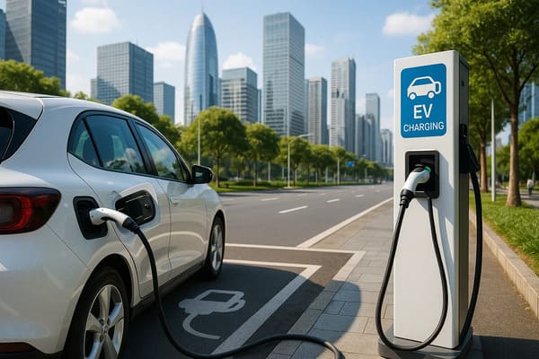
Practical deployment depends on vehicle compatibility, positioning,
maintenance and complete charging-system requirements.
How to Select a Pogo Pin EV Charging Interface
| Parameter | Engineering Question |
|---|---|
| Charging Application | Fleet dock, battery swap, autonomous shuttle or auxiliary interface? |
| Voltage | What operating and relevant transient voltage must the interface handle? |
| Current | What continuous and peak charging current is required? |
| Pin Map | Which contacts carry power, return, detection and control functions? |
| Working Stroke | What minimum, nominal and maximum compression will occur? |
| Docking Tolerance | What X, Y, Z and angular errors must the charging mechanism accommodate? |
| Mating Target | What geometry, material, finish and flatness are required? |
| Detection | How will the charger confirm a valid docking state? |
| Power Sequence | When should the main charging path be enabled and disabled? |
| Environment | What rain, dust, road debris, salt and temperature conditions apply? |
| Lifecycle | How many charging cycles are required and under what test conditions? |
| Maintenance | How will contacts and targets be inspected, cleaned and replaced? |
Recommended Validation Plan
| Validation Area | Recommended Evaluation |
|---|---|
| Docking Position | Evaluate minimum, nominal and maximum positioning error |
| Working Stroke | Measure contact compression across the charging array |
| Mechanical Load | Confirm vehicle and docking forces bypass the pogo contacts |
| Connection Detection | Verify normal, tilted and incomplete docking states |
| Power Enable | Confirm charging cannot begin before a valid connection state |
| Undocking | Verify charging current is removed before contact separation |
| Voltage Drop | Measure the complete intended charging path |
| Temperature Rise | Evaluate under required current, duty cycle and ambient conditions |
| Contamination | Test representative water, dust, salts and road debris |
| Repeated Docking | Monitor contact resistance, working stroke and target wear |
| Maintenance Recovery | Verify inspection, cleaning and contact replacement procedures |
Information Required for an NEV Charging Interface Review
| Project Input | Information to Provide |
|---|---|
| Vehicle Type | Passenger vehicle, shuttle, commercial fleet, industrial vehicle or other NEV |
| Charging Scenario | Automatic dock, battery swap, depot charger or project-specific interface |
| Voltage | Operating voltage and relevant system conditions |
| Current | Continuous current, peak current and charging duration |
| Pin Map | Function of each electrical contact |
| Working Stroke | Minimum, nominal and maximum compression |
| Docking Tolerance | X, Y, Z and angular alignment variation |
| Power Sequence | Detection, validation, charging enable and shutdown logic |
| Environment | Temperature, water, road debris, dust, salt and cleaning exposure |
| Lifecycle | Expected charging cycles and maintenance interval |
| Project Files | 2D drawing, 3D docking assembly, electrical architecture and target layout |
Frequently Asked Questions
What is a pogo pin EV charging solution?
It is a conductive charging interface that uses spring-loaded electrical
contacts between the charger and a vehicle, battery or removable module.
The pogo pins provide controlled contact compliance while the docking
system controls positioning and power sequencing.
Can pogo pins be used for automatic EV charging?
They can be evaluated for controlled automatic charging systems where the
vehicle and charger can establish repeatable mechanical alignment before
electrical power is enabled.
Are pogo pin EV chargers wireless?
No. Pogo pin charging uses direct conductive contact. Wireless charging
transfers energy without direct conductive power contacts.
Can pogo pins correct vehicle misalignment?
They can accommodate a controlled amount of movement along their spring
axis, but large lateral or angular errors should be corrected by the
docking mechanism.
Can charging start as soon as the pogo pins touch?
Not necessarily. A controlled system should verify the required mechanical
and electrical connection states before enabling the main charging path.
Can pogo pins carry high charging current?
They can form part of a higher-current conductive interface, but practical
current capability depends on the complete resistance path, number of
contacts, current sharing, termination, working stroke, temperature rise
and charging duty cycle.
Are pogo pin charging connectors waterproof?
Not automatically. Environmental protection depends on the complete
charging head, pogo pin feedthrough, vehicle-side target, seals, drainage
and test configuration.
How long does a pogo pin EV charging interface last?
Service life depends on working stroke, alignment, electrical load,
contamination, mating target, docking speed and maintenance. A cycle-life
claim should always include the test conditions.
Can pogo pin charging replace standard public EV charging connectors?
Not automatically. A custom pogo pin architecture is generally easier to
evaluate in controlled fleet, battery-swap or dedicated automated charging
environments where both sides of the interface are designed as one system.
Why are pogo pins useful for fleet charging?
Their spring-loaded contact architecture can support repeated automated
conductive connections where vehicles return to a defined dock and manual
plug handling is undesirable.
What information is needed for a custom NEV pogo pin charging interface?
Provide the vehicle and charging scenario, voltage, current, Pin Map,
docking tolerance, working stroke, power sequence, environmental
conditions, lifecycle target and mechanical drawings.
Request a Pogo Pin EV Charging Engineering Review
Explore

    pogo pin and spring-contact solutions

for charging, docking and project-specific electrical interfaces.

For magnet-assisted docking structures, review

    custom magnetic connector solutions
.

Submit the charging voltage, current, Pin Map, docking tolerance, working
stroke, environmental requirements and project drawings through the

    Get Quote & Samples page
.


    CTP can review pogo pin contact layout, working stroke, mating targets,
    mounting structure, magnetic or mechanical alignment and PCB, busbar,
    FPC or wire termination for custom NEV charging interfaces. Final
    current capability, voltage rating, charging safety, environmental
    protection and lifecycle depend on the complete customer charging
    system and project-specific validation.