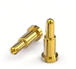
Engineering Summary:
Magnetic pogo pin life cycle should not be defined by one universal mating
cycle number. Connector service life depends on the pogo pin design,
working stroke, contact force, mating-target geometry, surface finish,
electrical load, contamination, alignment and environmental exposure.
A meaningful lifecycle claim should define the test conditions and the
electrical and mechanical criteria used to determine end of life.
Magnetic pogo pin life cycle should not be defined by one universal mating
cycle number. Connector service life depends on the pogo pin design,
working stroke, contact force, mating-target geometry, surface finish,
electrical load, contamination, alignment and environmental exposure.
A meaningful lifecycle claim should define the test conditions and the
electrical and mechanical criteria used to determine end of life.
What Does Magnetic Pogo Pin Life Cycle Actually Mean?
Magnetic pogo pin life cycle describes how long a defined connector
interface continues to meet its required mechanical and electrical
performance under repeated use.
It should not simply mean:
“How many times can the pogo pin physically move?”
A connector can continue moving mechanically while its electrical
performance has already degraded beyond the application requirement.
Depending on the project, end-of-life criteria may include:- contact resistance exceeding an approved limit;
- unstable or intermittent electrical contact;
- contact force falling outside specification;
- working stroke no longer moving freely;
- excessive mating-target wear;
- surface damage affecting electrical performance;
- magnetic retention falling outside the required range;
- temperature rise exceeding the validated limit under load;
- mechanical damage to the connector housing or contact structure.
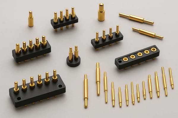
wear mechanisms, working strokes and lifecycle limits. Cycle claims
should therefore be tied to the specific connector design.
Cycle Count Is Not the Same as Service Life
A connector may be cycled thousands of times in a laboratory, but that
number has limited engineering value unless the test conditions are known.

A meaningful lifecycle result should identify:- connector revision;
- pogo pin structure;
- mating target;
- working stroke;
- contact force;
- mating speed;
- alignment condition;
- electrical load during mating and operation;
- ambient temperature and humidity;
- contamination or cleaning conditions;
- measurement interval;
- failure criteria.
Therefore:


    a model-specific cycle-life target validated under defined test conditions under one laboratory condition does not automatically
    mean 100,000 service cycles in a different product.
How Does a Magnetic Pogo Pin Wear Over Time?
Connector degradation is usually the result of several interacting
mechanisms rather than one sudden event.| Degradation Mechanism | Possible Effect |
|---|---|
| Contact Surface Wear | Changes contact geometry and surface condition |
| Target Pad Wear | Changes the mating surface and effective contact condition |
| Spring Fatigue | Can change contact force over repeated compression |
| Contamination | Can increase contact resistance or restrict plunger movement |
| Corrosion | Can alter conductive surfaces and mechanical components |
| Side Loading | Can accelerate plunger and barrel wear |
| Repeated Impact | Can damage targets, housings or contact geometry |
| Electrical Stress | Can increase local heating or damage during powered separation |
Lifecycle Degradation Is Usually Gradual
Connector failure does not always appear as a sudden open circuit.

A more realistic degradation sequence may look like:


    Initial Condition
    →
    Stable Operation
    →
    Surface Wear
    →
    Resistance Variation
    →
    Increasing Electrical / Mechanical Drift
    →
    Failure Criterion Reached


This is why lifecycle validation should track trends rather than only
checking whether electrical continuity still exists at the final cycle.
Strategy 1: Control the Recommended Working Stroke
Working stroke is one of the most important parameters affecting pogo pin
lifecycle.

The spring-loaded contact should operate within its approved compression
range after the connector reaches the final seated position.
A simplified relationship is:
S = Hfree - Hworkingwhere:
- S is actual compression;
- Hfree is the free contact height;
- Hworking is the installed working height.
| Stroke Condition | Possible Lifecycle Effect |
|---|---|
| Insufficient Compression | Unstable contact or higher resistance |
| Approved Working Stroke | Intended contact-force and mechanical condition |
| Excessive Compression | Higher mechanical stress, target wear or spring bottoming |
| Unequal Compression | Different wear rates across a multi-pin array |
Total Travel Is Not Recommended Working Stroke
The maximum distance a pogo pin can physically move should not automatically
be used as its normal operating position.

Mechanical stops should establish final connector position and prevent the
pogo pin from repeatedly reaching its mechanical limit.
Strategy 2: Match Contact Force to the Target and Application
More spring force is not automatically better for connector life.

Higher force can improve contact pressure in some conditions, but it can
also increase:- target-pad wear;
- plunger-tip wear;
- housing load;
- PCB or FPC stress;
- required magnetic retention;
- total reaction force in a multi-pin array.
Contact force should therefore be specified at the intended working stroke,
not as an isolated spring specification.
Multi-Pin Arrays Create a Total Spring Reaction Force
When several contacts are compressed simultaneously, the mating structure
must react against the combined spring load.
A simplified relationship is:
Ftotal ≈ F1 + F2 + ... + Fn

This total force influences magnetic retention, housing stiffness and final
working stroke.
Strategy 3: Design the Mating Target as Part of the Lifecycle System
Pogo pin life cannot be evaluated independently from the mating target.

Every mating cycle affects both surfaces.
Target design should consider:
- pad size;
- surface finish;
- flatness;
- target material;
- mechanical support;
- pogo pin tip geometry;
- allowed surface marking;
- environmental exposure.
A connector may appear acceptable while the target surface gradually
develops wear that changes the electrical interface.
Tip Geometry Changes the Wear Mechanism
Flat, rounded, pointed, crown and other pogo pin tip geometries interact
differently with mating surfaces.

A sharper contact may generate greater local pressure, while a broader
contact can distribute force across a larger area.

Neither approach is universally better. The correct geometry depends on the
target surface, contamination, electrical load and lifecycle requirement.
Strategy 4: Control Lateral Motion During Magnetic Mating
Magnetic attraction can make a connector easier to mate, but uncontrolled
capture can produce sideways motion as the two halves approach.

Repeated lateral sliding may accelerate wear on both the pogo pin tip and
mating target.
A preferred mating sequence is:
    Approach
    →
    Magnetic Capture
    →
    Mechanical Guidance
    →
    Final Alignment
    →
    Controlled Pogo Compression


Housing geometry and mechanical datums should therefore control the final
position rather than relying on the pogo pins themselves to correct
alignment.
Magnetic Attraction Should Not Create Repeated Impact
Excessive closing velocity or poorly controlled magnetic capture can cause
the two connector halves to strike each other repeatedly.

Depending on the product, this may contribute to:- target indentation;
- housing wear;
- tip deformation;
- connector noise or undesirable user feel;
- greater shock transmitted into the PCB or product structure.
The objective is therefore controlled capture rather than simply maximizing
magnetic attraction.
Strategy 5: Select Materials and Surface Finishes for the Actual Wear Environment
Material and plating choices influence connector lifecycle, but there is no
universal material stack that supports a specific number of mating cycles.
Selection can depend on:
- working stroke;
- contact force;
- tip geometry;
- mating target;
- current;
- temperature;
- contamination;
- corrosion exposure;
- required lifecycle.
Spring material, plunger material, barrel material and surface finish should
therefore follow the approved product drawing and endurance validation
rather than generic rules such as “more gold always means longer life.”
Plating Thickness Alone Does Not Define Connector Life
Surface finish is only one variable in the wear system.

Even a durable surface can wear prematurely if:- working stroke is excessive;
- the connector mates at an angle;
- abrasive debris is trapped between the contacts;
- the target finish is incompatible with the wear mechanism;
- the contact experiences excessive sliding.
Plating should therefore be evaluated together with the complete contact
mechanics.
Strategy 6: Treat Environment as Part of the Endurance Test
A connector tested only in a clean indoor environment may behave very
differently after exposure to moisture, sweat, dust, oils, salt or other
contaminants.

Environmental exposure can change:- contact resistance;
- surface friction;
- corrosion behavior;
- plunger movement;
- mating-target condition;
- magnet surfaces;
- housing dimensions or sealing materials.

degradation. Environmental life should be evaluated under the conditions
expected in the actual application.
Environmental Sealing Does Not Automatically Mean Longer Contact Life
Sealing can reduce some forms of environmental exposure, but a connector
with an ingress-protection rating can still experience mechanical wear,
contact contamination or target degradation.

Likewise, a flat magnetic interface does not automatically establish an IP
rating.

Environmental performance should apply only to the defined and tested
assembly.
Magnets Have Their Own Environmental Requirements
The magnetic system should be evaluated separately from the pogo pin
electrical contacts.
Relevant factors can include:
- magnet material;
- coating;
- temperature exposure;
- moisture or corrosion exposure;
- mechanical retention inside the housing;
- changes in seated retention over time.
A connector can therefore remain electrically functional while its magnetic
retention changes, or retain magnetic force while the electrical contact
system has degraded.
Strategy 7: Define End-of-Life Criteria Before Testing Begins
An endurance test needs a clear PASS / FAIL definition before the first
cycle begins.

Otherwise, a final number such as “a model-specific cycle-life target validated under defined test conditions” has little engineering
meaning.| Lifecycle Metric | Example Evaluation |
|---|---|
| Contact Resistance | Track value and variation against an approved limit |
| Working Stroke | Confirm free movement and required compression |
| Contact Force | Monitor force at the defined stroke |
| Voltage Drop | Measure under the intended electrical load |
| Temperature Rise | Compare against the validated thermal limit |
| Target Wear | Inspect surface condition and dimensional change |
| Plunger Condition | Inspect tip wear, movement and damage |
| Magnetic Retention | Track seated and separation behavior where relevant |
| Intermittent Contact | Monitor transient opens or unstable electrical states |
Measure Degradation Throughout the Test — Not Only at the End
If measurements are taken only at cycle zero and at the final cycle, the
test provides limited information about how the connector degraded.

A stronger validation program records performance at defined intervals.
For example, engineers may monitor:
- initial baseline condition;
- early-life behavior;
- intermediate cycle points;
- late-life degradation;
- end-of-life condition.
The exact interval should follow the project requirements and expected
degradation mechanism.
Contact Resistance Trend Can Reveal Degradation Before Open Failure
One useful lifecycle indicator is the change in contact or complete-path
resistance over repeated mating.

A connector can still pass continuity while resistance becomes less stable.

Trending resistance can help engineers identify:- surface wear;
- contamination;
- changes in working stroke;
- target degradation;
- increasing variability between cycles.
However, resistance measurement should be performed under a defined contact
state, temperature and measurement method.
Electrical Load Can Change the Meaning of the Lifecycle Test
An unpowered mechanical endurance test and a powered endurance test answer
different questions.| Test Type | What It Primarily Evaluates |
|---|---|
| Unpowered Cycling | Mechanical wear and repeated mating behavior |
| Powered While Seated | Electrical and thermal behavior during repeated service |
| Powered Mating / Separation | Additional electrical stress during contact transition |
A high cycle count achieved under zero electrical load should therefore not
automatically be used to describe a connector that will repeatedly
disconnect under significant current.
High Current Can Accelerate Electrical Degradation
Higher contact resistance produces additional voltage drop and heating
under current.
A simplified relationship is:
Vdrop = I × Rpathand:
Ploss = I² × Rpath

This means a relatively small increase in resistance can become more
important as current increases.

Lifecycle testing for power contacts should therefore include the intended
electrical and thermal conditions where relevant.
Parallel Contacts Can Age at Different Rates
Multi-pin magnetic connectors may use several pogo pins in parallel for
power or return.

These contacts do not necessarily share current equally.

Differences in working stroke, target condition, PCB routing and contact
resistance can cause one branch to carry more current than another.

Over time, unequal loading can also create different wear and thermal
histories between contacts.

Lifecycle validation should therefore consider the complete array rather
than assuming every pogo pin experiences identical conditions.
Self-Wiping Does Not Mean Self-Cleaning
Some contact geometries create a small amount of relative movement between
the pogo pin and target.

This movement can disturb some surface films, but it does not ensure removal of:- dust;
- oil;
- sweat residue;
- abrasive particles;
- corrosion products;
- metallic debris.
Abrasive contamination can actually increase wear during repeated mating.Magnets Can Attract Metallic Debris During the Product Lifetime
Permanent magnets can attract ferromagnetic contamination toward the mating
interface.

Over repeated cycles, metallic particles may:- scratch mating targets;
- restrict complete seating;
- change working stroke;
- bridge adjacent contacts;
- increase contact resistance.
Cleaning access and contamination management should therefore be included
in the lifecycle design.
Maintenance Can Be Part of the Lifecycle Strategy
In some applications, the connector does not need to remain untouched for
its entire service life.

A maintenance plan may include:- visual inspection;
- approved cleaning procedure;
- target-surface inspection;
- contact-resistance checks;
- verification of pogo pin movement;
- replacement of contact or target modules;
- magnetic-debris removal.
Designing the contact interface as a replaceable or serviceable module can
be more practical than attempting to make every contact last for the entire
product lifetime.
Lifecycle Should Include the Mating Target, Not Only the Pogo Pin
A common endurance-test mistake is replacing the target during testing while
continuing to count pogo pin cycles.

If the actual product uses the same target for its entire service life, the
target should normally be included in the endurance system being evaluated.

Otherwise, the test may underestimate target wear and contamination effects.
Use Statistical Life Claims Carefully
Testing one sample until failure does not establish the lifetime
distribution of an entire production population.

If an engineering team needs a statistical reliability statement, the test
plan should define:- sample quantity;
- lot selection;
- test conditions;
- failure definition;
- censored samples;
- appropriate statistical analysis.
Lifecycle statements should therefore distinguish between:- a single-sample endurance result;
- a qualification test;
- a production acceptance requirement;
- a statistical field-life prediction.
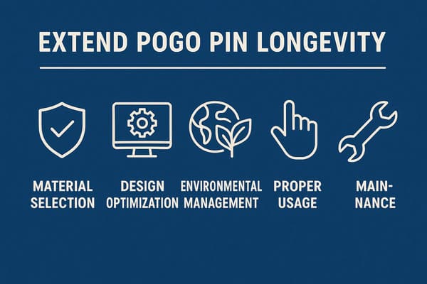
environmental degradation rather than relying on one material or cycle
count alone.
Recommended Magnetic Pogo Pin Lifecycle Test Plan
| Validation Area | Recommended Evaluation |
|---|---|
| Baseline | Record initial dimensions, contact resistance, force and retention |
| Working Stroke | Verify minimum, nominal and maximum compression |
| Mating Target | Use the actual target geometry and finish |
| Mating Motion | Reproduce intended speed, angle and alignment |
| Electrical Load | Define whether cycling is powered or unpowered |
| Resistance Trend | Measure at defined cycle intervals |
| Contact Force | Monitor changes at the defined working stroke |
| Target Wear | Inspect surface condition during the endurance test |
| Plunger Wear | Inspect contact-tip and movement condition |
| Magnetic Retention | Track seated and separation behavior where relevant |
| Environment | Include representative temperature, humidity and contamination |
| Temperature Rise | Evaluate where the connector carries meaningful current |
| Failure Criteria | Define electrical and mechanical end-of-life limits before testing |
Information Required for a Lifecycle Engineering Review
| Project Input | Information to Provide |
|---|---|
| Application | Charging, docking, wearable, medical, industrial or other interface |
| Pin Count | Number and electrical function of contacts |
| Working Stroke | Minimum, nominal and maximum compression |
| Contact Force | Required force at the intended stroke |
| Mating Target | Geometry, material, finish and flatness |
| Electrical Conditions | Voltage, continuous current and peak current |
| Mating Motion | Approach direction, speed and expected misalignment |
| Magnetic Behavior | Capture, seated retention and separation requirement |
| Environment | Temperature, humidity, water, sweat, dust, oil or other contaminants |
| Lifecycle Target | Required mating cycles and intended service profile |
| Failure Criteria | Maximum resistance, minimum force, wear or other end-of-life limits |
| Maintenance | Cleaning, inspection and replacement strategy |
| Project Files | 2D drawing, 3D assembly, PCB layout or connector specification |
Frequently Asked Questions
How long does a magnetic pogo pin connector last?
There is no universal lifecycle for every magnetic pogo pin connector.
Service life depends on working stroke, contact force, target geometry,
mating motion, electrical load, environment and the failure criteria used
during testing.
Can magnetic pogo pins last 100,000 or one million cycles?
A specific connector may achieve a defined endurance result, but the cycle
number is meaningful only when the connector revision, working stroke,
mating target, electrical load, environment and pass/fail criteria are
documented.
What is the biggest factor affecting pogo pin life?
There is no single factor for every design. Working stroke, side loading,
mating-target condition, contact force, contamination and electrical load
can all significantly affect lifecycle.
Does thicker gold plating always increase pogo pin life?
No. Surface finish is only one part of the wear system. Mating motion,
target finish, working stroke, contamination and contact force also affect
durability.
Does stronger magnetic force increase connector life?
Not automatically. Excessive attraction can increase mating impact or
lateral sliding. Magnetic capture and retention should be balanced with the
spring array and mechanical interface.
Can waterproofing extend pogo pin life?
Environmental sealing can reduce some forms of moisture or contamination
exposure, but it does not eliminate mechanical wear. Final environmental
performance depends on the complete tested assembly.
Why does contact resistance increase after repeated mating?
Possible causes include target wear, contact-tip wear, contamination,
corrosion, changes in working stroke or changes in contact force. The
complete interface should be inspected before attributing the change to one
component.
Should pogo pin lifecycle testing be powered or unpowered?
It depends on what the test is intended to represent. Unpowered cycling
primarily evaluates mechanical endurance, while powered testing can also
reproduce electrical and thermal stresses expected in service.
Should the mating target be replaced during lifecycle testing?
If the real product uses the same mating target throughout service, keeping
the target in the test provides a more representative evaluation of the
complete contact pair.
When has a pogo pin reached end of life?
End of life occurs when the defined connector fails one or more approved
electrical or mechanical acceptance criteria, such as excessive resistance,
unstable contact, insufficient spring force, excessive wear or inadequate
magnetic retention.
How can magnetic pogo pin service life be extended?
Control working stroke, select appropriate contact force and target
geometry, minimize uncontrolled lateral sliding, choose materials for the
actual environment, manage contamination and define a representative
endurance-validation program.
Request a Magnetic Pogo Pin Lifecycle Engineering Review
Explore

    custom magnetic connector solutions

for removable charging, docking and device interfaces.

Review

    pogo pin and spring-contact solutions

for different working strokes, contact layouts and termination structures.

Submit the working stroke, mating target, electrical load, environmental
conditions, expected mating cycles and project drawings through the

    Get Quote & Samples page
.


    CTP can review pogo pin working stroke, contact-force requirements,
    mating-target geometry, magnetic capture, electrical load and lifecycle
    test conditions for custom magnetic connector projects. Final service
    life should be defined through the approved connector design,
    application-specific test conditions and documented end-of-life
    criteria.