An IP68 magnetic connector should be treated as a complete sealing system,
not as a waterproof pogo pin, magnet or gasket. A prototype can pass an
ingress test and still become unreliable in production if feedthroughs,
enclosure joints, gasket compression, cable exits, exposed contacts or
manufacturing variation are not controlled. The most useful design method
is to map every possible ingress path, define the connector state being
protected and verify electrical and mechanical performance after
environmental exposure.
IP68 Is a System Requirement, Not a Material Property
Engineers sometimes describe individual design features as “IP68”:- an IP68 pogo pin;
- an IP68 magnet;
- an IP68 O-ring;
- an IP68 insert-molded housing.
That language can hide an important engineering distinction.

Ingress protection applies to a defined enclosure or assembly under a
defined test configuration.

A magnetic connector normally contains several potential environmental
boundaries:


    External Environment
    →
    Contact Surface
    →
    Pogo Feedthrough
    →
    Connector Housing
    →
    Device-Housing Joint
    →
    PCB / FPC / Cable
    →
    Protected Electronics


If any one of those boundaries is uncontrolled, the complete interface can
fail even when another part of the connector is well sealed.

This is why the useful engineering question is not:

“Is this pogo pin waterproof?”
It is:
    “What is the complete sealing boundary, and where can water or dust
    bypass it?”
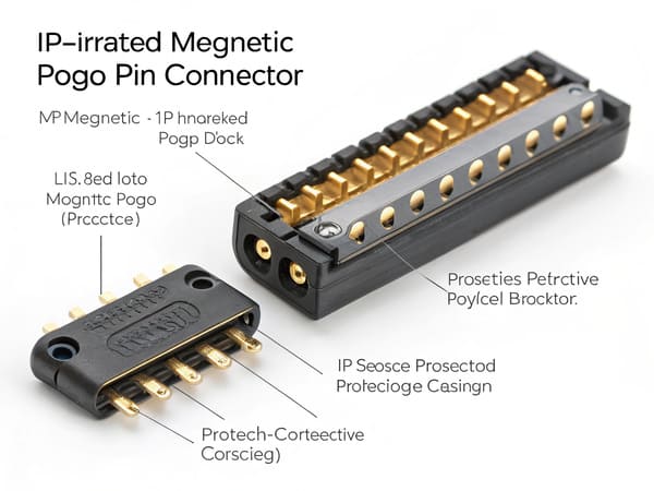
enclosure boundary rather than as an isolated pogo pin or gasket.
Before Looking for Leaks, Define the Connector State
Removable magnetic connectors can exist in several different states:| Connector State | Engineering Question |
|---|---|
| Fully Mated | Is the intended sealing boundary completely engaged? |
| Partially Mated | Can water reach contacts before complete seating? |
| Unmated | Are the exposed device-side contacts allowed to become wet? |
| Wet Reconnection | What happens if the connector is attached while moisture remains? |
| Post-Cleaning | Can fluid or residue remain around the mating surface? |
A connector that protects the internal enclosure while fully mated may have
completely different electrical behavior while unmated.

Therefore:


    Enclosure Ingress Protection
    ≠
    Dry Exposed Contacts
    ≠
    Safe Wet-State Electrical Operation


These requirements should be specified separately.
Failure Path 1: Leakage Through the Pogo Pin Feedthrough
The first potential leak path exists where the conductive contact passes
through the connector housing.

This location is challenging because the design must maintain an electrical
path while preventing fluid from traveling around the stationary contact
structure.
Possible sealing approaches
Depending on the architecture, engineers may use:
- insert molding;
- overmolding;
- potting;
- adhesive sealing;
- mechanical interference features;
- integrated molded barriers.
None of these processes should automatically be treated as proof of a
specific ingress rating.
Why feedthrough seals fail
Potential causes can include:
- insufficient bonding area;
- poor material adhesion;
- molding voids;
- flash or incomplete fill;
- thermal expansion mismatch;
- mechanical loading during assembly;
- process variation.
A prototype produced with carefully selected components may pass while
normal production variation exposes a small leakage path.
Design question
Ask:


    If fluid reaches the outside of the pogo pin barrel, what physical
    feature prevents it from reaching the internal electronics?


The answer should be visible in the cross-section or controlled process,
rather than assumed from the word “insert-molded.”
Failure Path 2: Leakage Between the Connector Module and Device Housing
A sealed pogo pin feedthrough does not protect the product if water can pass
around the entire connector module.

This creates a second sealing boundary:


    Connector Module
    ↔
    Product Housing
Possible interfaces include:
- gasketed flange;
- O-ring groove;
- adhesive bond;
- overmolded joint;
- mechanically compressed seal;
- potted interface.
The seal is only as good as the mating surfaces
Even a well-selected gasket can fail if the surrounding structure has:- insufficient flatness;
- housing warpage;
- surface defects;
- inconsistent fastener load;
- uneven mechanical support;
- incorrect groove geometry.
Therefore, environmental design should include the connector-to-device
interface—not only the connector supplier's internal structure.
Failure Path 3: Gasket Compression Falls Outside the Real Tolerance Window
A sealing element does not work simply because it appears compressed in
nominal CAD.

The real seal compression changes across manufacturing tolerance.
A simplified relationship is:
    Actual Seal Compression
    =
    Nominal Compression
    ±
    Housing Tolerance
    ±
    Connector Tolerance
    ±
    Gasket Tolerance
    ±
    Assembly Variation


Engineers should therefore review:


    Minimum Compression
    /
    Nominal Compression
    /
    Maximum Compression
Too little compression
Potential consequences include:
- incomplete sealing contact;
- local leakage paths;
- sensitivity to housing warpage;
- reduced margin after aging.
Too much compression
Potential consequences can include:
- seal damage;
- excessive assembly force;
- housing deformation;
- higher reaction force;
- increased stress on adjacent structures.
Magnets should not be used as uncontrolled compression stops
In a magnetic connector, the final sealing position should normally be
controlled by mechanical geometry.
A stronger sequence is:
    Magnetic Capture
    →
    Mechanical Guidance
    →
    Mechanical Stop
    →
    Defined Seal Compression
    →
    Defined Pogo Working Stroke


Magnetic attraction can provide retention, but it should not independently
determine the final seal compression.
Failure Path 4: The Cable, FPC or PCB Exit Bypasses the Main Seal
Engineers sometimes spend significant effort sealing the visible connector
face while overlooking the termination side.

A magnetic connector may terminate through:- PCB;
- FPC;
- individual wires;
- multi-core cable;
- overmolded cable assembly.
Each path can create a separate environmental boundary.Cable interfaces require more than external overmolding
Water can migrate through:- the cable-to-housing interface;
- gaps between conductors;
- poor potting adhesion;
- cracks created by cable flexing;
- strain-relief damage;
- process voids.
The cable exit should therefore be treated as part of the connector sealing
system rather than as a separate cosmetic feature.
PCB interfaces also require a boundary definition
A surface-mounted pogo connector sitting on a PCB is not automatically a
waterproof PCB interface.

The engineer should identify whether water is allowed to reach:- solder joints;
- PCB pads;
- vias;
- internal board surfaces;
- other components.
The environmental boundary may therefore need to extend beyond the
connector itself.
feedthroughs, housing joints and cable or PCB interfaces.
Failure Path 5: The Internal Electronics Are Sealed but the Exposed Contacts Are Not Managed
One of the most important distinctions in a magnetic pogo pin interface is:


    protecting the electronics from water is not the same as protecting
    exposed electrical contacts from wet-state failure.


A device can maintain an enclosure ingress rating while external contact
pads remain exposed.
Possible wet-state risks include
- temporary conductive paths between contacts;
- electrochemical activity on energized surfaces;
- residue after evaporation;
- corrosion;
- unstable contact resistance;
- contaminated reconnection.
These risks depend on the actual fluid, voltage, spacing, electrical state,
surface condition and exposure duration.
Power-state strategy matters
In some products, the system architecture can distinguish:


    Connector Absent
    →
    Contacts Unpowered / Limited State
    →
    Magnetic Capture
    →
    Mechanical Seating
    →
    Connection Detection
    →
    Validation
    →
    Main Power Enable


Not every application needs this architecture.

The important engineering principle is that magnetic attachment does not
have to mean immediate full-power operation.
Drainage and drying should be intentional
A shallow magnetic contact surface can simplify access, but geometry should
still be reviewed for:- water trapping;
- capillary gaps;
- low points;
- residue accumulation;
- debris retention.
“Flat” does not automatically mean self-draining.Failure Path 6: Contamination Prevents Full Seating Before the Seal Is Established
IP protection is usually discussed as a water problem, but contamination
can become a mechanical sealing problem first.

Dust, sand, fibers or metallic particles can prevent the connector from
reaching its intended final position.
This can change:
- seal compression;
- pogo pin working stroke;
- magnetic retention;
- contact resistance;
- target contact area.
Magnetic connectors have an additional debris mechanism
Ferromagnetic particles can be attracted toward the mating surface.Accumulated particles may:
- hold the connector above its mechanical stop;
- prevent full gasket compression;
- scratch target surfaces;
- bridge adjacent conductive regions;
- retain moisture near contacts.
Therefore, contamination testing should represent the real environment
where metallic debris is credible.
Self-wiping should not be interpreted as self-cleaning
Some contact geometries produce limited wiping motion during mating.

That does not mean the interface automatically removes:- metal fragments;
- sticky residue;
- corrosion products;
- oil films;
- environmental deposits.
Cleaning access and maintenance requirements may still need to be defined.Failure Path 7: The Prototype Seal Works but Production Variation Does Not
This is where many environmental designs become manufacturing problems.

One carefully assembled prototype can pass while production units contain
variation in:- molded dimensions;
- housing flatness;
- gasket position;
- adhesive volume;
- potting coverage;
- insert-molding quality;
- connector height;
- magnet position;
- assembly force.
Environmental qualification must therefore be transferred into production
controls.
Turn the seal design into measurable CTQs
| Sealing Requirement | Possible Production CTQ |
|---|---|
| Final Connector Position | Installed height / datum position |
| Gasket Compression | Gap or compressed-height control |
| Feedthrough Seal | Molding or potting process characteristic |
| Housing Interface | Flatness / geometry / assembly condition |
| Pogo Working Stroke | Installed minimum / nominal / maximum compression |
| Magnetic System | Polarity, location and required retention behavior |
Visual inspection alone cannot prove ingress performance
AOI or visual inspection can detect selected:- missing components;
- assembly orientation;
- visible molding defects;
- selected dimensions.
It does not automatically prove the integrity of an internal sealing path.

The production-control strategy should therefore match the actual failure
mechanism.
Passing an IP Test Is Not the End of Validation
An environmental test answers an important question:


    Did the defined assembly satisfy the required ingress condition?


A connector project may also need to answer:


    Did the interface still perform correctly after the exposure?
Post-exposure checks may include
- contact resistance;
- complete-path voltage drop;
- temperature rise;
- pogo pin movement;
- working stroke;
- contact force;
- surface corrosion;
- magnetic retention;
- housing condition;
- seal damage.
The required checks depend on the actual product function.Do Not Confuse IP Protection with Corrosion Qualification
An ingress test and a corrosion test answer different engineering questions.

A connector may prevent water from entering the electronics while external
contacts are still exposed to:- salt;
- sweat;
- cleaning agents;
- industrial chemicals;
- condensation;
- corrosive residue.
Therefore:


    IP Test
    ≠
    Salt Exposure Test
    ≠
    Chemical Compatibility Test
    ≠
    Field-Life Prediction


These should be specified independently where required.
The Magnet Is Also Part of the Environmental Design
Permanent magnets can require their own protection strategy when exposed to
moisture or aggressive environments.

Possible controls may involve:- appropriate magnet material selection;
- surface coating;
- encapsulation;
- housing isolation;
- adhesive selection;
- drainage design.
A coated magnet should not automatically be described as a hermetically
sealed magnet.

The complete magnet environment and expected exposure should be reviewed.
Seven IP68 Magnetic Connector Failure Paths at a Glance
| Failure Path | Main Risk | Engineering Control |
|---|---|---|
| 1. Pogo Feedthrough | Fluid bypasses the contact-to-housing interface | Controlled molding, potting or sealing architecture |
| 2. Connector-to-Housing Joint | Water bypasses the entire connector module | Defined joint, flatness and seal geometry |
| 3. Gasket Compression | Tolerance produces insufficient or excessive seal compression | Minimum / nominal / maximum stack analysis |
| 4. PCB / FPC / Cable Exit | Termination becomes an alternative ingress path | Define the complete backside sealing boundary |
| 5. Exposed Contacts | Wet-state electrical or corrosion risk remains outside the enclosure | Power-state, drainage and exposed-contact design |
| 6. Contamination | Debris prevents final seating or seal compression | Contamination management and representative testing |
| 7. Production Variation | A passing prototype is not consistently reproduced | CTQs, process controls and production validation |
A Better IP68 Magnetic Connector Validation Workflow
Rather than beginning with an O-ring or a material specification, use the
following process:


    Define Environmental Requirement
    →
    Define Mated / Unmated State
    →
    Draw the Sealing Boundary
    →
    Map Every Leak Path
    →
    Calculate Seal and Stroke Tolerances
    →
    Define Wet-State Electrical Behavior
    →
    Build Prototype
    →
    Environmental Test
    →
    Post-Test Electrical / Mechanical Check
    →
    Pilot Production
    →
    Production CTQ Control
Prototype Review Checklist
| Review Area | Question |
|---|---|
| Sealing Boundary | Can the complete protected volume be traced on a cross-section? |
| Feedthrough | How is fluid prevented from traveling around each conductive path? |
| Housing Joint | How is the connector module sealed to the final enclosure? |
| Compression | What are minimum, nominal and maximum seal conditions? |
| Pogo Stroke | Does every tolerance condition remain inside the working window? |
| Termination | Can water bypass the connector through PCB, FPC or cable interfaces? |
| Unmated State | What happens when exposed contacts become wet? |
| Contamination | Can dust or metallic debris prevent full seating? |
| Post-Test | Which electrical and mechanical parameters are checked after exposure? |
| Production | Which seal characteristics are controlled as CTQs? |
When IP68 May Not Be the Right Requirement
A higher-sounding IP code should not be selected simply as a marketing
target.

Engineers should begin with the actual product exposure:- indoor dust;
- rain;
- temporary water exposure;
- immersion;
- washdown;
- condensation;
- salt water;
- cleaning chemicals.
Different environmental threats may require different validation methods.

The product specification should follow the actual mission profile rather
than selecting IP68 simply because it appears more robust.
Information Required for an IP68 Magnetic Connector Review
| Project Input | Information to Provide |
|---|---|
| Protected Boundary | Which electronics or enclosure volume must remain protected? |
| Connector State | Mated, unmated, partial or multiple required states |
| Exposure | Dust, water, condensation, salt, sweat or chemicals |
| Mechanical Envelope | Available X, Y and Z space |
| Working Stroke | Minimum, nominal and maximum pogo compression |
| Seal Structure | Gasket, potting, overmold or other boundary |
| Magnetic Behavior | Capture and retention requirements |
| Pin Map | Power, return, detection and signal functions |
| Electrical Load | Voltage, current and duty cycle |
| Termination | PCB, FPC, wire or cable structure |
| Lifecycle | Expected mating and environmental exposure profile |
| Project Files | 2D drawing, 3D assembly and enclosure cross-sections |
Frequently Asked Questions
What is an IP68 magnetic connector?
The term generally describes a magnetic connector used as part of a defined
assembly that has been designed and validated for an IP68 ingress-protection
requirement. The rating should be tied to the actual tested configuration
rather than to the presence of magnets or pogo pins alone.
Are magnetic pogo pins automatically IP68?
No. Spring-loaded contacts and magnets do not automatically create an
ingress-protection rating. The complete feedthrough, housing, seal,
termination and enclosure boundary must be considered.
Does insert molding make a pogo pin connector IP68?
Not by itself. Insert molding can form part of the sealing architecture, but
molding quality, material adhesion, housing geometry and the remaining leak
paths still require validation.
Does an O-ring supports IP68 protection?
No. Seal performance depends on geometry, compression, mating-surface
quality, tolerance stack, aging and assembly condition.
Should magnets compress the waterproof gasket?
Magnetic attraction can contribute to connector retention, but final gasket
compression should normally be defined by controlled mechanical geometry
rather than uncontrolled magnetic closing force.
Can an IP68 connector have exposed electrical contacts?
A product can protect the electronics behind the connector while external
contacts remain exposed. The exposed-contact state and wet-state electrical
behavior should therefore be evaluated separately from enclosure ingress.
What happens if an IP68 magnetic connector is connected while wet?
The result depends on contact spacing, voltage, fluid contamination, power
state and system architecture. Wet reconnection should be treated as a
separate operating or fault state when it can occur in the real product.
Why can an IP68 connector prototype pass while production units fail?
Production variation in molding, gasket position, housing dimensions,
potting, installed height or assembly force can create leak paths that were
not present in a carefully built prototype.
Does IP68 prove corrosion resistance?
No. Ingress protection and corrosion resistance are different engineering
questions. Salt, sweat, chemicals and residues may require separate
material and environmental validation.
Does IP68 prove the connector will survive outdoors for years?
No. An ingress result should not be converted directly into a field-life
prediction. Long-term performance also depends on UV, temperature cycling,
contamination, corrosion, mating wear and the real service environment.
Should electrical performance be checked after an IP test?
When electrical functionality matters, post-exposure checks such as contact
resistance, voltage drop, temperature rise or contact movement can help
determine whether the connector remained functional after environmental
testing.
What information should I provide for a custom IP68 magnetic connector?
Provide the protected enclosure boundary, required connector states,
environmental exposure, mechanical envelope, Pin Map, working stroke,
electrical load, sealing concept, termination method and available 2D or
3D product files.
Request an IP68 Magnetic Connector Engineering Review
Explore

    CTP custom magnetic connector solutions

for removable charging, docking and sealed interface architectures.

Review

    pogo pin and spring-contact connector solutions

for different contact layouts and mounting structures.

Learn more about CTP engineering and manufacturing capabilities on the

    About Us page
. Submit your enclosure cross-section, connector envelope, Pin Map,
working stroke, required connector state, environmental exposure,
termination structure and available 2D or 3D files to CTP for an
engineering review.
The interface can be reviewed by mapping the complete sealing boundary
and potential ingress paths before the connector geometry and tooling
are frozen.
Final ingress protection, wet-state electrical behavior, corrosion
resistance, lifecycle and production capability should be confirmed
against the approved connector revision and defined validation
conditions.
CTP ENGINEERING PATHS
Choose the right path for your project
Move from application requirements to a connector pair, a data-capable cable assembly, or a charging cable configuration. Final specifications are confirmed against an approved drawing and project validation plan.
Magnetic Connectors
Connector geometry, pin layout, mechanical integration and OEM/ODM review.
Engineering overview → 02Magnetic Data Cables
Power and signal allocation, cable exit, interface selection and assembly review.
Cable engineering → 03Magnetic Charging Cables
Browse the complete cable catalog and shortlist a starting structure for customization.
View cable catalog →