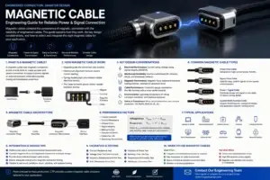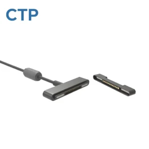
Magnetic connectors have changed how devices charge and exchange data. One motion, no fumbling with ports, and a clean breakaway if someone trips over the cable. But a magnet does not know which contact carries power and which carries ground. Without magnetic polarity coding , a multi-pin magnetic connector can snap together in the wrong orientation, shift by one contact, or even mate with a similar charger from another product.
The result is often reverse-polarity damage: shorted rails, overheated contacts, a dead charging circuit, or a field return that is hard to diagnose. This guide explains how polarity coding works, how to combine it with other keying methods, and how to build a multi-pin magnetic connector that is safe to use even when users make mistakes.
What Is Magnetic Polarity Coding?
Magnetic polarity coding is the deliberate arrangement of magnet poles (north and south) inside a connector pair so that only the correct orientation can mate. Opposite poles attract and like poles repel. If the male and female halves carry matching, complementary pole patterns, the connector pulls itself into the right position. If the user rotates it or flips it, the like poles face each other, and the connector pushes away instead of locking on.
In other words, the magnets do two jobs at once. They provide retention force, and they act as a magnetic key that rejects the wrong connection before the contacts ever touch.
Why Wrong-Mating Happens in Multi-Pin Magnetic Connectors
Most wrong-mating problems come from design symmetry. Common causes include:
- Symmetric pin layouts. A round connector with evenly spaced contacts can mate in several rotational positions, and each position may connect power to the wrong pin.
- Reversible geometry. A rectangular housing with no visual or mechanical cue can be flipped 180 degrees.
- Offset mating. Strong magnets can pull a connector one contact position off center, especially on small wearable devices.
- Look-alike accessories. Two products from the same brand may use similar magnetic heads with different pin maps.
- Foreign metal. Keys, coins, or steel tools can bridge exposed contacts.
The more contacts in the connector, the more ways a wrong mate can occur. A 2-pin design has a small number of failure modes. A 6-pin design with power, ground, data, and sense lines has many more.
How Magnet Pole Arrangement Works as a Mechanical Key
The core idea is simple: assign a fixed pole to each magnet position and make the mating half its mirror image.
Two-magnet pattern. Place one magnet with its north pole facing out and one with its south pole facing out. The mating half carries the opposite pattern. The correct orientation attracts at both positions. A 180-degree flip turns both into repulsion.
Three- or four-magnet pattern. Add magnets in an asymmetric arrangement, such as NSS or NNSS. A rotated or shifted connector now sees at least one repelling pair, which blocks the mate.
Contact-aligned magnets. Place magnets close to the contact zones so the pull force is strongest exactly where alignment matters. This helps the pogo pins land on the correct pads instead of drifting.
Two cautions apply. First, repulsion must be strong enough for the user to feel it, but weak enough not to make the connector feel broken. Second, magnet placement affects nearby components, so review the layout for interference with compass and Hall sensors in the host device.
Combine Polarity Coding with Physical Keying and an Asymmetric Pin Map
Polarity coding works best as part of a layered strategy, not as the only protection. Strong magnetic connector designs usually combine three layers:
- Magnetic key. Pole arrangement rejects the wrong orientation by repulsion.
- Mechanical key. A projecting tongue, groove, step, or shaped outline physically blocks a wrong mate and guides the correct one. Guided designs also reduce the sideways slip that causes partial contact.
- Asymmetric pin map. Arrange contacts so that even a misaligned mate cannot connect power to a signal line. Place power and ground contacts on one side, data on the other, and avoid mirror-symmetric layouts.
A useful rule: if the pin map is mirror-symmetric, the connector needs stronger mechanical and magnetic keying. If the pin map is asymmetric, the design is already safer, and the keying simply reinforces it.
Reverse Polarity Protection: The Electrical Safety Net
Even with good keying, a connector will eventually meet an unexpected situation. Electrical reverse polarity protection for a magnetic connector is the safety net that limits the damage. Common methods include:
- Series Schottky diode. Simple and cheap, but it adds a voltage drop and wastes power in high-current charging.
- P-channel MOSFET (ideal diode). Blocks reverse voltage with a much lower voltage drop, which makes it a better fit for battery-powered and high-current products.
- Bridge rectifier. Accepts either polarity, but adds loss and size. It suits low-power designs where orientation-agnostic mating is a feature.
- Resettable fuse or current limiting. Limits fault current if contacts are bridged or mismatched.
- Sense or detect pin. The charger keeps the power contacts off until a dedicated pin confirms a valid mate, so exposed contacts are not live in open air.
The detect-pin approach is especially useful on the cable side. A powered charging head with exposed contacts is a risk around coins, jewelry, and sweat, and a handshake keeps it safe until the correct device is attached.
Design Checklist for 2-Pin, 4-Pin and 6-Pin Layouts
Use this checklist when specifying a custom connector or reviewing a drawing.
2-pin connectors
- Use an N/S magnet pair so the reverse orientation repels.
- Make the contact layout non-symmetric, or add a small mechanical guide.
- Add a diode or MOSFET if the product is user-facing.
4-pin connectors
- Separate power and ground from data contacts.
- Use an asymmetric magnet arrangement (not NSNS in a perfectly symmetric square).
- Consider a guide shape so it cannot be rotated by 90 degrees.
6-pin and multi-pin connectors
- Prefer a rectangular outline with a projecting tongue or step.
- Place at least one sense pin for mate detection.
- Add polarity coding and an asymmetric pin map at the same time, not one or the other.
All layouts
- Confirm voltage, current, mating direction, and available space before choosing a structure.
- Test wrong-orientation and offset mating during sampling, not only the correct mate.
- Verify pull force, repulsion force, and contact alignment with real samples.
- Check magnetic interference with sensors in the host product.
Common Mistakes to Avoid
- Relying on polarity alone. Magnets can be overpowered by a user hard or by a nearby steel part.
- Making repulsion too weak. If the wrong mate only feels slightly different, users will force it.
- Ignoring look-alike products. Different products in one family should not share the same pole pattern and pin map.
- Skipping electrical protection. A keyed connector can still meet a faulty charger or a shorted cable.
- Testing only the happy path. Qualification should include flipped, rotated, and shifted mates.
Frequently Asked Questions
Does magnetic polarity coding fully prevent wrong mating?
It greatly reduces it, but it should be combined with mechanical keying and electrical protection for best results.
Can polarity-coded connectors be made for wearables?
Yes. Compact round and rectangular designs can use small magnets in an N/S pattern, often with a guide tongue to keep alignment on small devices.
Is reverse polarity protection still needed if the connector is keyed?
Yes. Keying prevents most wrong mates, but protection circuitry covers faults, look-alike accessories, and unexpected use.
Can I order a custom magnetic connector with a specific pole pattern? Yes. OEM and ODM projects can define pole arrangement, pin count, shape, and cable termination around the device requirements.