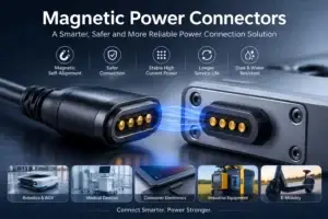
Should the dock let go when someone lifts the device, or should the user release a lock first? That question does more to narrow the connector choice than a photograph of the mating face. A handheld accessory returned to its stand throughout the day has a different routine from equipment that must stay connected until an operator deliberately unlocks it.
A magnetic vs latched docking connector decision is therefore about the intended release action as well as contact layout. CTP develops magnetic mating components in round and linear formats, with different mounting structures. Those options are useful where magnet-assisted attachment fits the product’s routine. A project needing positive mechanical locking may require a latch or a separate retention system instead.
Magnetic docking suits a deliberate place-and-lift routine
Magnets can help bring matching parts together and hold them in the intended seated relationship. The electrical pressure comes from the contact system; the device and connector geometry establish the installed position. The attraction you feel is not proof that the correct contacts have engaged or that the circuit is compatible.
For an instrument used briefly and returned to a desktop stand, a simple lift-off action can be attractive. The operator does not have to find a locking tab each time. The designer still needs to confirm capture, seated retention and separation behaviour for the actual device and cable route.
A round single-contact pair offers a compact mating form
Our round high-retention connector pair, CTP-MPC-1P-RD-HR-A01, combines a central spring contact with a circular magnetic structure. It is a format to explore when a compact round mating point suits the product and the required separation behaviour can be defined.
This is a single-contact interface. A power application needs its complete return path defined elsewhere in the circuit; a product name is not a complete wiring diagram. The magnetic retention and the electrical function should be reviewed as separate parts of the design.
A mounting base holds the connector to the device, not the two devices together
Five inline contacts can sit on a defined attachment base
The CTP five-contact connector with mounting base, CTP-MPC-5P-SR-MB-A01, places five contacts in a row with magnetic structures beside the contact area and a base with through-holes. It gives the enclosure designer visible attachment features to develop with the device.
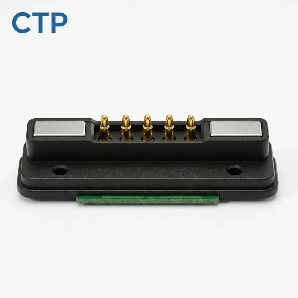
That distinction matters in a dock. Fastening the receiver securely to the cradle does not turn the magnetic mating interface into a positive latch. It can, however, make the receiver’s location easier to define while the connector pair and the product guides establish how the device sits.
For a compact diagnostic accessory used on a bench, the five paths may serve the approved power and control allocation. The base helps relate that connection to the enclosure. Any claim about separation force or environmental performance needs the selected drawing and validation conditions.
A seven-contact circular pair gives an industrial layout another route
Our seven-contact round magnetic connector, CTP-MPC-7P-RD-IND-A01, uses a circular metal housing and a recessed spring-contact structure. It provides a different shape and contact count for equipment whose electrical allocation and available mounting space favour a round interface.
For a service instrument with a detachable lead, that can be a useful structure to compare with a long contact row. The housing gives the mechanical team a defined outline to integrate. Its appearance should not be treated as a verified vibration, waterproof or locking specification.
Picture the same round connection on two products: a light accessory lifted from a desk, and a taller instrument gripped near its top. The user’s hand applies a different leverage to each assembly. A comfortable release at the connector cannot be decided from magnetic attraction alone. Checking the complete product in its normal removal direction lets the team judge the action that people will actually feel. CTP’s round pair and mounting-base row give you different shapes to develop around that action, so the electrical interface can fit the product rather than dictate its proportions.
Latched docking becomes useful when release must be a separate action
If an installation must remain connected when the cable is tugged, a positive lock may fit the job better than a deliberately detachable magnetic interface. That does not make a latch universally better. It changes what the person using the device must do and how a cable load reaches the surrounding structure.
| Daily action | Design question |
|---|---|
| Lift an accessory from its stand often | Can the magnetic interface release comfortably in the intended direction? |
| Keep a connection secured until authorised removal | Is a positive latch or separate mechanical restraint required? |
| Route a lead beside a moving operator | What should happen if the lead is pulled unexpectedly? |
Magnetic systems can be designed with break-away behaviour, as Rosenberger’s magnetic connector explanation describes for its own products. That is a design principle, not a measured break-away promise for every CTP component. The release requirement needs to be agreed for your assembly.
Tell the manufacturer how the dock should attach and release
CTP’s magnetic connector range offers several physical starting points for a custom interface. We can review the contact count, housing shape, mounting and mating requirements together. Where a latch is essential, state that early so the overall retention design is not built around the wrong assumption.
Our magnetic connector pull-force discussion takes the release question further, with the user’s action and the complete product arrangement in view.
Bring a sketch of the seated device and show the normal removal direction. Describe what should happen during an accidental pull as well. That small amount of context helps turn “strong magnets” or “secure docking” into a connection that behaves the way the product’s users expect.