A prototype can look connected from the outside while leaving the important contact surfaces hidden from view. Once the device is sitting in a cradle, the engineer may have nowhere to attach a sense lead, inspect the seating or see whether a cable is pushing the mating parts apart. Fixing that after the fixture is built can be more work than choosing the connector itself.
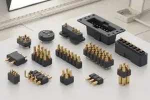
Magnetic connector test fixture access should cover three places: the mating interface, the rear termination and the points needed for the intended measurement. CTP supplies contact modules and connector blocks with different layouts and termination directions. They give the fixture designer several physical routes to consider without assuming that every product is a dedicated automated-test probe.
Magnetic connector fixture access begins around the seated device
For an accessory that docks magnetically, leave a way to observe the receiver in the position in which it will actually operate. A fixture that holds the parts differently can produce a reassuring measurement while missing a seating problem in the finished housing. The support should reproduce the intended assembly without obscuring every useful view.
It can help to separate the mechanical fixture from the measuring connections. The cradle locates the device; defined terminals or test pads provide access to the circuit. Forcing an extra probe between the working contact and its target can change the contact pressure you intended to evaluate.
A thirty-nine-contact module brings many paths into one interface
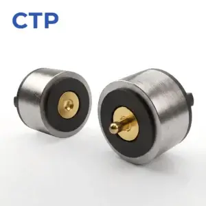
The CTP thirty-nine-contact module, catalogue reference CTP-P3932, offers a dense multi-contact arrangement with a flexible circuit connection. It is a product format to review where a prototype needs many separately assigned paths within a defined interface.
The contact count makes channel identification especially important. Match the physical viewing direction to the numbered circuit drawing, then place the measuring access where each intended path can be reached. A dense module does not, by itself, provide a test multiplexer, measurement accuracy or a particular data protocol.
Rear termination can decide how useful the fixture will be
Twelve through-hole contacts can connect to an accessible fixture board
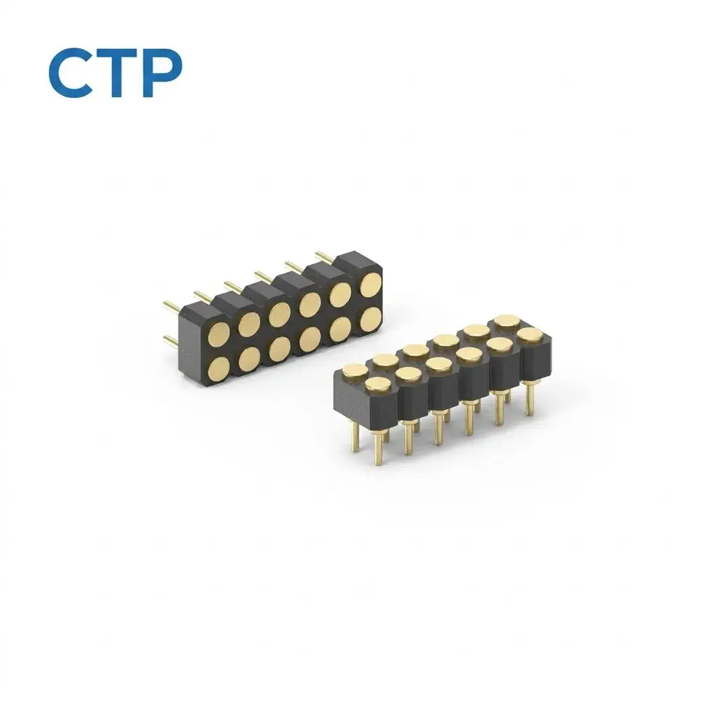
Our twelve-contact through-hole connector, CTP-PC-12P-DR-A01, uses a six-by-two arrangement with straight PCB tails. A designer can place that connector on a fixture board whose own pads or terminals remain accessible behind the mating area.
This is useful when the fixture needs to keep wiring orderly rather than bring loose leads directly to every spring contact. The connector footprint and board support need to be developed together, with the installed contact position set by the chosen part drawing.
A ten-contact right-angle block moves the board connection out of the mating direction
The CTP ten-contact right-angle connector, catalogue reference CTP-P3577, combines a five-by-two contact arrangement with bent PCB tails. It offers a different geometry where the fixture board cannot sit directly behind the device-facing contact surface.
For example, a small magnetic receiver may need an unobstructed approach from above while the fixture electronics sit beside it. A right-angle contact structure is worth reviewing in that layout. The important benefit is the change in direction, not an assumption that the connector tolerates any sideways load.
Four solder-cup contacts give a harness its own termination route
Our four-contact solder-cup connector, CTP-PC-4P-DR-A01, uses a two-by-two layout with rear cups intended for wire termination. It can suit a fixture whose measurement leads or harness need to be arranged separately from a PCB footprint.
Keep the lead support separate from the working plungers. Pulling on a wire should not change the connector’s seated position during a reading. The permitted wire size, joint construction and strain support belong to the fixture’s agreed design.
Keep connector access tied to the measurement you need
A continuity check, a low-resistance measurement and a temperature assessment do not necessarily use the same access points. Decide which part of the path is under review before choosing where the fixture leads will land. Otherwise the result may include a cable or joint that another team has excluded from its comparison.
For a many-channel sensor accessory, label the fixture from the same contact view used in the product drawing. For a simple charging receiver, leave enough room to verify the power and return paths without bridging adjacent contacts. Both projects benefit from access that can be used repeatedly without dismantling the entire setup.
A photograph of the twelve-contact block from its tail side will reverse the apparent row order compared with a mating-face view. Label both views explicitly on the fixture drawing. That makes the accessible board pads useful to the next person taking a measurement, without asking them to reconstruct the connector’s orientation.
Specialist test probes also have their own contact tips and operating conditions; Harwin’s ATE probe information illustrates that distinction. The CTP components described here are connector and module options for a project-defined fixture, not a claim of identical test-probe performance.
Give the connector manufacturer a view of the fixture as well as the device
When CTP reviews a custom contact assembly, the space behind the mating face can be as useful as the front outline. Show the fixture board or harness, the seated device and the points the team needs to inspect. That makes it easier to compare straight tails, bent tails and solder-cup routes against the actual layout.
The same part identification matters when the sample arrives; our pogo pin incoming-inspection article explains how to keep that review tied to the agreed configuration.
Our project support route covers drawings, sample configuration and validation requirements. Leave the measuring access visible in those drawings. The best fixture is not the one that hides the most wiring; it is the one that lets the team understand the connection without changing it to take a reading.