Custom Magnetic Connector Modules
A custom magnetic connector module combines the mating interface with the structures needed to install it inside a real device. Depending on the project boundary, the module may include pogo pin contacts, magnets, a molded carrier, PCB or FPC, cable conductors, termination, sealing features and inspection points as one controlled assembly.
- Connector + FPC or PCB
- Magnet + housing integration
- Cable or board termination
- Assembly and inspection definition
When Does a Connector Become a Custom Module?
A standard connector ends at the connector housing or contact terminals. A custom module extends the supply boundary into the customer's device by combining several interdependent parts into one drawing, one assembly route and one inspection specification.
This category is useful when changing the connector also changes the PCB, FPC, cable, housing, magnet position, sealing or assembly process. It should not duplicate the standard Magnetic Connector or Magnetic Cable categories.
Define What Belongs Inside the Supplied Module
Many custom-module delays begin because the customer and supplier assume different boundaries. Confirm which items are supplied, which are reference geometry and which remain part of the customer's final-device assembly.
Contact Interface
- Pogo pins and mating pads
- Pin count and functional map
- Working compression and sequence
- Contact layout and pitch
Mechanical Structure
- Carrier, housing and mounting datum
- Magnet location and polarity
- Keys, stops and alignment guides
- Device-side fixation features
Electrical Breakout
- PCB, FPC, wire or cable
- Pin-to-circuit mapping
- Connector or termination at the opposite end
- Shielding, ground and test access
Assembly & Verification
- Molding, soldering, adhesive or potting
- Critical dimensions and force checks
- Continuity and polarity inspection
- Packaging and traceability boundary
Common Integrated Structures for Custom Device Projects
The structure is selected from the device assembly and electrical path. These are engineering architecture types, not fixed off-the-shelf ratings.
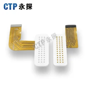
Connector with Flexible Circuit Breakout
Useful when the mating interface must connect to a remote PCB, wrap around an enclosure feature or fit through a narrow internal route.
- FPC outline, bend zone and stiffener
- Pad mapping and termination definition
- Assembly access and strain control
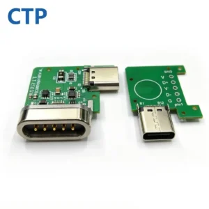
Connector Mounted on a Dedicated Board
Useful when the module requires routing, test pads, components, mounting holes or a standardized board-to-device interface.
- Board thickness and copper design
- Mounting datums and board support
- Current, ground and test routing
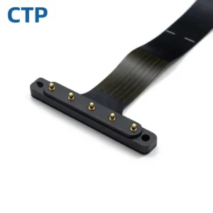
Connector with Internal Pigtail or Harness
Useful when the device-side path requires flexible routing but the project does not need a complete external magnetic charging cable.
- Wire gauge, length and color map
- Outlet direction and strain relief
- Opposite-end terminal or connector
Connector Integrated with the Device Barrier
Useful when sealing, potting, insert molding or a flat external contact surface must be developed together with the device housing.
- Seal path and leakage boundary
- Material and process compatibility
- Assembly-level validation condition
Multi-Row or High Contact Count Assembly
Useful when contact allocation, PCB routing and available area require a dense multi-row, circular or custom-array structure.
- Contact budget and return paths
- Insulation and routing space
- Force balance across the array
Mating Interface with Guides and Mounting Features
Useful when the device needs blind mating, a charging dock, a removable module or controlled release as a complete mechanical interaction.
- Approach path and capture range
- Magnetic force and spring reaction
- Device mass and pull direction
Freeze the Interfaces Before Freezing the Individual Parts
The most important document is not only the connector drawing. A module project needs an agreed interface-control definition between the mating side, internal electrical path, device enclosure and customer's assembly process.
Interface-control items
- Mating datum: where the two halves locate before contact compression begins.
- Compression window: minimum and maximum plunger position across the tolerance stack.
- Electrical map: every contact, conductor, FPC/PCB pad and opposite-end terminal.
- Magnetic definition: pole direction, orientation, holding force and release direction.
- Mechanical boundary: screw, clip, adhesive, molding, potting or housing features supplied by each party.
- Inspection boundary: what is tested at module level and what remains for final-device validation.
Information Needed to Start a Custom Module Review
Unknown values can be marked as targets, but electrical functions, available geometry and the expected supply boundary should be discussed before drawing release.
| Input area | What to provide | Module decisions affected | Recommended format |
|---|---|---|---|
| Device geometry | Available length, width, height, mating direction, PCB/FPC position and assembly access | Housing, contact layout, module outline, mounting and cable route | STEP/IGES, section view and dimensioned 2D drawing |
| Electrical interface | Voltage, current profile, contact functions, ground, detection, control, signal and selected data | Pin count, contact allocation, PCB/FPC routing, conductor and thermal design | Pin map, block diagram or interface table |
| Mating behavior | Blind mating, target holding or release force, orientation, pull direction and device mass | Magnets, spring-force balance, guides, keys and capture geometry | Use scenario, force target and mating sketch |
| Internal breakout | PCB, FPC, wire, cable, length, opposite-end connector and test access | Module supply boundary, routing, termination and assembly sequence | Harness drawing, PCB/FPC file or connection diagram |
| Environment | Water, sweat, cleaning, dust, corrosion, temperature, vibration and expected lifecycle | Materials, plating, sealing process and validation plan | Environmental specification or risk list |
| Production plan | Prototype quantity, pilot build, annual volume, assembly method, traceability and change control | Tooling, process design, inspection, packaging and production release | Forecast, build schedule and quality requirements |
Move the Module Through Four Controlled Decisions
The purpose of each gate is to freeze the interfaces needed by the next activity, rather than repeatedly changing every part at the same time.
Architecture Review
Confirm product family, module boundary, pin map, available envelope, mating behavior and the main environmental risks.
Interface & DFM Review
Confirm datums, tolerance stack, compression, magnet layout, PCB/FPC or cable routing, assembly access and tooling direction.
Prototype Verification
Check fit, polarity, continuity, force, voltage drop, temperature rise, cable mechanics and relevant environmental conditions.
Production Release
Freeze drawings, materials, approved samples, critical dimensions, inspection methods, packaging and engineering-change control.
What Must Be Controlled on the Released Module Drawing?
Physical and electrical definition
- Overall module outline and mounting datums.
- Pin map, polarity and terminal or wire mapping.
- Pogo pin free height, working height and approved travel.
- Magnet direction, position and mating orientation.
- PCB/FPC outline, cable length and outlet direction.
- Critical clearances, insulation and contact spacing.
Production and quality definition
- Materials, plating, adhesive, potting or molding specification.
- Controlled dimensions and measurement datums.
- Continuity, polarity, resistance or project-specific electrical checks.
- Magnetic holding/release and compression-force inspection where required.
- Appearance, marking, packaging and traceability requirements.
- Drawing revision and supplier/customer change-approval route.
Use the Standard Product Page When a Full Module Is Not Required
These links prevent the module category from competing with the four core product families. Choose the narrowest supply scope that solves the project.
Questions About Integrated Connector Modules
Is a custom module the same as a magnetic cable assembly?
Not always. A cable assembly normally focuses on the external cable, magnetic head, conductors and opposite-end termination. A custom module may be an internal device subassembly that combines the connector with a PCB, FPC, carrier, magnets, sealing and mounting features.
Can an existing magnetic connector be integrated into a new FPC or PCB module?
It may be possible when the contact layout, working compression, available space, electrical allocation and assembly process are compatible. The connector still needs a fit, tolerance, routing and DFM review before the new module drawing is released.
Who should design the FPC or PCB used inside the module?
Either party can own the design, but ownership and approval must be clear. The interface should define pin mapping, outline, layer or conductor needs, bending or support zones, termination, test pads and the customer's final connection to the device electronics.
Can waterproofing be included in the supplied module?
Sealing features, potting, insert molding or a device-barrier concept can be included, but the final protection level depends on the complete module, customer housing, mating state, cable outlet and test condition. The module boundary and final-device validation must be agreed separately.
What makes a module suitable for mass production?
The structure must have controlled datums, realistic tolerances, stable assembly access, approved materials, measurable critical characteristics, electrical and mechanical inspection methods, packaging and a defined change-control process. A functional handmade prototype alone is not a production release.
What should I submit for an initial module review?
Send the device application, available 3D envelope, pin map, current and signal requirements, PCB/FPC or cable boundary, target mating behavior, environmental conditions, quantities and available STEP, IGES, PCB/FPC, harness or 2D drawings.
REPRESENTATIVE CUSTOM MODULES
Review Published Custom Magnetic Module Examples
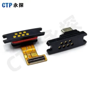
Use these published examples to compare contact density, module geometry and integration direction. Final dimensions and electrical requirements are confirmed against the approved project drawing.