Products develop over time. A compact instrument gains another function, a dock moves to a different position, or an accessory needs a tidier cable route. A custom connection is valuable when it can be considered alongside those changes, with a clear view of what the product should keep and what needs to adapt.
Our magnetic connector range includes several contact counts, mounting styles and complete cable formats. Connector engineering change approval brings those physical and electrical choices together when a design evolves. The goal is a connection that continues to fit the device naturally, rather than a change made to one small part without considering the rest.
Our mounting-base design gives the interface a defined place in the product
The CTP five-contact magnetic connector, CTP-MPC-5P-SR-MB-A01, combines five inline spring contacts with a mounting base and through-holes. Magnetic features sit beside the contact row, assisting capture and seated retention.
The base makes the mechanical attachment part of the connector’s visible structure. For a dock or device enclosure, that offers a clear outline to arrange with the surrounding supports. The spring contacts serve the electrical interface while the base relates the connector body to the product.
A five-contact row leaves room for more than a basic power pair
A product may use the additional positions for detection, identification, control or supported signals according to its circuit. That makes the format worth considering when a new device function needs its own path across the removable interface.
Imagine an instrument whose original accessory only supplied power. A later version may need to recognize the attached accessory as well. A contact layout with additional assigned positions gives the electronics team another way to build that function into a single connection area.
The connector does not create the detection function on its own. Its advantage is the available set of paths within a defined body. The device circuit and contact map determine how those paths are used in the revised product.
An eight-contact pair can keep several functions along one edge
Our eight-contact single-row magnetic pair, CTP-MPC-8P-SR-MH-A01, has eight inline positions, a pogo side, a flat target side and mounting ears with through-holes. It presents a complete mating arrangement to integrate with the device.
Mounting ears help relate the pair to a dock or enclosure
A removable module may need a defined contact edge rather than a socket placed wherever the board happens to allow. The elongated connector and its attachment features give the designer one structure to compare with that edge. The matching target half can be arranged with the module itself.
When the device housing changes, the important benefit of a clear interface definition is knowing which relationships matter. The contact pattern, target position and mechanical attachment can be considered together, so a new enclosure shape is developed around the intended connection.
This is a practical way to approach a product refresh. The outside of the device may change while some useful internal relationships remain. A defined connector pair makes those relationships easier to see and discuss than an informal combination of separate contacts and mounting details.
A dual-row format offers a different shape for a more capable module
The CTP fourteen-contact magnetic pair, CTP-MPC-14P-DR-A01, uses a seven-by-two arrangement. It offers more electrical positions in a rectangular pattern instead of extending them all in a single line.
A larger control module might benefit from that different layout when additional functions are introduced. The connector can bring the assigned paths into one contact area, allowing the rest of the product to be arranged around a coordinated interface.
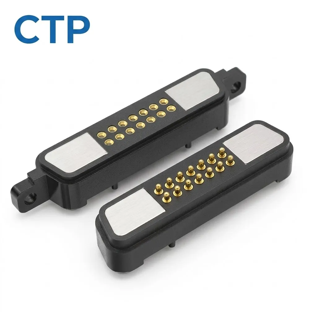
Changing from a single row to a dual row is a genuine interface change, so it belongs with the matching target and housing. The product opportunity is the additional layout choice. It gives the team another way to make room for useful functions while keeping the contact area concentrated.
That does not mean every product upgrade needs more contacts. If the five-contact interface still serves the device, keeping its useful geometry may be preferable. The range allows the choice to follow the product’s functions and available area.
Cable formats can adapt the connection route inside and outside the device
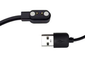
Sometimes the mating face is already in the right place, but the cable route needs attention. Our four-contact USB-C magnetic cable, CTP-MCC-4P-USBC-DATA-01, includes the source plug, cable, magnetic head and matching PCB-side connector.
A complete USB-C-ended assembly keeps the route easy to picture
For a desktop accessory, that format lets the source end and magnetic device connection be considered together. Cable length, conductor arrangement and outlet direction can be developed around the installation. A tidier route can make the accessory feel more intentional beside the finished product.
The six-contact magnetic harness assembly, CTP-MCC-6P-LIN-WH-01, offers another route. It combines a linear magnetic interface, six conductors and an opposite-end harness connector. This is worth comparing when the magnetic head needs to connect to electronics within a larger enclosure.
For a redesigned dock, the harness can be considered with the distance between the head and the internal board. The connector face remains at the user’s attachment point, while the lead follows the available space behind it. That is a different product benefit from a fixed external USB-ended accessory.
Wire construction and contact allocation are specific to the selected assembly. If either changes, the electrical definition changes with it. Keeping the complete cable map clear makes the physical flexibility useful without assuming that similar-looking cables are interchangeable.
Connector engineering change approval can protect the parts users already like
Consider a compact instrument that is gaining a larger display. The internal board may move, while the accessory connection should remain in the same convenient position on the enclosure. A harness-based assembly is a different option from a connector fixed directly to the main board. Its value lies in giving the product another route between those two locations.
The six-conductor CTP harness provides a defined magnetic face and an opposite-end connector to consider in that arrangement. The cable can be developed around the board’s new position. The contact map remains tied to the device circuit, so the physical route and the electrical functions are discussed as parts of one assembly.
A different product might need more assigned paths while retaining a narrow connection edge. The eight-contact inline pair can then be compared with the five-contact mounting-base design. If the available area is shorter and deeper, a dual-row format offers a different shape. These are choices about making the revised product work comfortably, rather than simply changing a component number.
For the buyer, a clearly identified revised configuration also makes repeat orders easier to discuss. The mounting features, contact map and cable format describe the actual item wanted. That is more helpful than relying on a photograph when the visible face may remain similar across different electrical definitions.
The same clarity helps when deciding which older accessories remain suitable. A familiar magnetic shape may be worth preserving, but compatibility belongs to the complete electrical and mechanical arrangement. Defining that arrangement lets the product team retain the benefits of its existing connection where they still fit the new device.
A product revision does not have to begin by replacing the whole connection concept. It can start with the qualities worth keeping: a convenient attachment point, a compact target area, a familiar source plug or a mounting arrangement that fits the enclosure.
For the five-contact mounting-base design, that might mean preserving the useful contact location while refining the surrounding housing. For the six-contact harness, it might mean keeping the magnetic face while developing a different internal cable route. The actual change is defined for the project and reviewed with the mating side.
A simple before-and-after view of the selected interface is often more helpful than a long generic change form. It shows the affected contact positions, mounting features and wire destinations in the context of the device. The approval then describes a specific product configuration.
Our sample approval guide offers more detail for projects moving from a proposed revision to a physical sample. Agreeing the relevant approval steps and records around the actual order keeps the review focused on the configuration your product will use.
The value of the range is having concrete alternatives when the product needs them. A mounting-base connector, an inline mating pair, a dual-row interface and two different cable formats each support a different arrangement. A considered change keeps the connection useful to the device and familiar to the person using it.