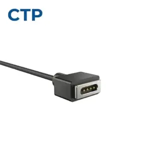
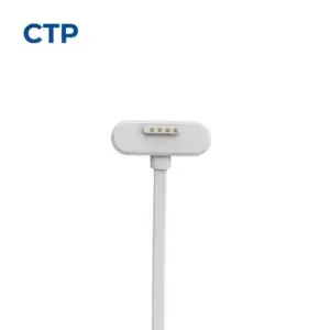
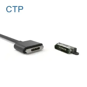
Magnetic Mating Interface
Confirm Pin count, contact allocation, magnet arrangement, connector shape, polarity control and mating direction.
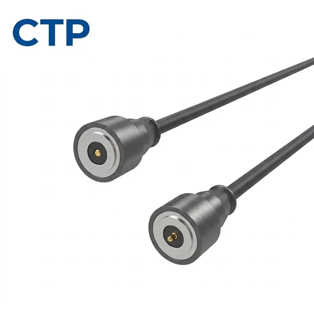
A custom 1 pin round magnetic charging cable with a recessed central contact and concentric outer mating structure. The electrical function of the outer ring and the complete return path must be defined by the approved wiring diagram. Voltage, current capability, cable construction, opposite-end termination, contact travel and magnetic retention are project-specific.
The finished assembly must define the magnetic mating component, internal conductor arrangement, cable construction and the opposite-end connection as one complete electrical system.
Confirm Pin count, contact allocation, magnet arrangement, connector shape, polarity control and mating direction.
Define cable length, conductor count, wire specification, shielding requirements, jacket and flexibility.
Select USB, Type-C, DC plug, bare wire, terminal, PCB connection or another customized termination.
Confirm installation space, outlet direction, strain relief, exposed-contact state and user operation.
1 PIN RECESSED ROUND MAGNETIC CHARGING CABLE
This 1 pin round magnetic charging cable is a complete cable assembly with one central electrical contact, a recessed circular mating face and a visible concentric outer ring.
The term “1 Pin” identifies the central contact count. It does not by itself define the complete charging circuit. The electrical function of the outer ring or any other return-path structure must be confirmed by the approved wiring diagram.
Magnets primarily assist capture and retention during mating. Final position, alignment and seating should be established by the circular housing and mechanical mating geometry rather than magnetic attraction alone.
The visible charging head uses a round housing with a recessed mating face. One central electrical contact is visible inside the recessed area, together with a concentric outer ring.
The recessed geometry can be evaluated when a device requires a compact circular charging interface and the housing must help control final mating position and contact protection.
Pin Count One central electrical contact
Interface Shape Round / circular
Mating Face Recessed concentric geometry
Primary Function Project-defined charging interface
A charging interface requires a complete conductive loop. One visible central contact therefore does not by itself define the complete power and return architecture.
The approved wiring diagram should identify the electrical function of the central contact, the concentric outer ring and any additional conductive structure used to complete the circuit.
If the outer ring is used as the return path, its contact material, surface finish, mating geometry, cable connection and interface resistance should be evaluated as part of the complete electrical system.
If the outer ring is not an electrical contact, another defined return path is required.
Center Contact Function → To Be Confirmed
Outer Ring Function → To Be Confirmed
Complete Return Path → Defined by Approved Wiring Diagram
The magnetic structure assists the charging head during approach and helps retain the interface after engagement.
Capture force, retention force, separation force and peel force describe different mechanical conditions and should not be represented by one undefined magnetic-force value.
Final position, alignment and seating should be controlled by the circular housing, mechanical datums and mating surfaces. Magnetic attraction alone should not define the final electrical contact condition.
Stronger magnetic retention is not automatically better. The required holding and release behavior should be selected around the device structure, cable handling and intended separation direction.
The product image confirms one central electrical contact position, but the internal spring-loaded structure and mechanical travel cannot be determined from appearance alone.
If the center contact uses a pogo pin, the approved drawing should define the working stroke, total travel, spring force and installed compression condition.
Working stroke and total travel are different parameters. Working stroke defines the intended operating compression, while total travel represents the available mechanical movement of the spring-loaded contact.
The mating housing should establish the final mechanical seating condition. A spring contact should provide electrical connection and controlled Z-axis compliance rather than serve as the primary mechanical hard stop.
Charging-current capability cannot be determined from the center-contact diameter, round housing size or one-pin description alone.
Power Source → Opposite-End Termination → Cable Conductors → Round Magnetic Cable Head → Center Contact + Confirmed Return Path → Device-Side Interface → PCB / Charging Circuit → Battery / Load
Vdrop = I × Rpath
Ploss = I² × Rpath
Cable length, wire gauge, termination resistance, center-contact resistance, return-path resistance, mating condition, device-side PCB copper and temperature rise should be evaluated together before a continuous-current rating is released.
Continuous current and peak current should be defined separately when the charging system includes transient or intermittent loading.
The round magnetic charging head is only one part of the complete cable assembly.
Cable length, conductor count, wire gauge, conductor material, outer jacket, strain relief and opposite-end termination should be defined together with the charging requirements of the device.
USB-A, USB-C, DC plug, terminal, bare wire or another custom interface should only be stated after the approved cable drawing confirms the actual configuration.
A round housing, recessed mating face or visible sealing feature does not by itself establish a waterproof or dust-protection rating.
Environmental protection must be evaluated for the defined complete assembly, including the cable head, mating component, device enclosure, seals, installation condition and test configuration.
An IP rating should only be published after the relevant complete assembly has been defined and validated to the required test level.
Contact corrosion behavior, cable durability and environmental capability should also be specified separately from the IP rating.
| Specification | Details |
|---|---|
| Product Type | 1 Pin Recessed Round Magnetic Charging Cable |
| Pin Count | 1 Pin |
| Primary Function | Charging |
| Interface Shape | Round / Circular |
| Mating Face | Recessed Concentric Geometry |
| Contact Geometry | One Central Contact + Concentric Outer Ring |
| Center Contact Type | To Be Confirmed |
| Outer Ring Electrical Function | To Be Confirmed |
| Return Path | Defined by Approved Wiring Diagram |
| Magnetic Function | Capture + Retention |
| Final Position / Alignment | Controlled by Mechanical Mating Geometry |
| Cable Length | Project-Specific |
| Opposite-End Termination | To Be Confirmed |
| Voltage | Project-Specific |
| Continuous Current | To Be Confirmed |
| Peak Current | To Be Confirmed |
| Current Capability | Validate Complete Conductive Path |
| Working Stroke | To Be Confirmed |
| Total Travel | To Be Confirmed |
| Spring Force | To Be Confirmed |
| Magnetic Retention | Project-Specific |
| Male / Female Definition | To Be Confirmed |
| Material / Plating | To Be Confirmed |
| Cycle Life | To Be Confirmed |
| Operating Temperature | To Be Confirmed |
| IP Rating | To Be Confirmed at Complete Assembly Level |
CTP can review the complete one-pin recessed round magnetic charging cable around the customer’s electrical, cable, mechanical and environmental requirements.
Explore related Round Magnetic Cable Connectors for alternative circular magnetic cable architectures.
This 1 pin recessed round magnetic charging cable can be evaluated for devices requiring a compact detachable power interface with a circular mating geometry.
Final application suitability depends on the complete charging path, return-path design, cable construction, mechanical interface, magnetic behavior and environmental requirements.
It refers to the one central electrical contact visible in the round mating interface. It does not by itself define the complete number of conductive paths in the charging circuit.
The complete return path must be defined by the approved wiring diagram. The function of the concentric outer ring or any other conductive return structure should be confirmed before the cable architecture is released.
A concentric outer ring is visible, but its electrical function cannot be confirmed from appearance alone. Its function should be defined by the approved wiring and mechanical drawings.
The image confirms one central electrical contact position, but the spring-loaded mechanism, working stroke and total travel should be confirmed from the contact drawing.
Charging current is project-specific and must be validated across the complete conductive path, including the cable conductors, source termination, center contact, confirmed return path, device-side interface and charging circuit.
This should not be assumed from the circular appearance. Permitted rotation depends on the electrical function of the center contact and outer ring, polarity requirements and the approved mechanical design.
The magnetic structure primarily assists capture and retention. Final position, alignment and seating should be controlled by the mechanical mating geometry.
An IP rating should only be stated for a defined and validated complete assembly. The cable head, mating component, device enclosure, sealing structure and test configuration should be confirmed before publishing an IP rating.
Yes. Cable length, wire construction, cable outlet and opposite-end termination can be defined according to the approved project requirements.
Provide the center-contact function, outer-ring function, complete return path, voltage, continuous and peak current, cable length, wire gauge, opposite-end termination, connector dimensions, contact travel, magnetic requirements, environmental requirements and available 2D or 3D drawings.
CUSTOM ROUND MAGNETIC CHARGING CABLE DEVELOPMENT
Send CTP your center-contact and outer-ring functions, complete return-path design, voltage, continuous and peak current, cable length, wire gauge, opposite-end termination, round mating dimensions, contact requirements, magnetic requirements and environmental validation scope. Our engineering team can review the complete charging interface before quotation and sample development. Request Custom Quote & Samples
This product page presents a CTP magnetic cable assembly configuration for engineering reference. Final dimensions, electrical ratings, materials, magnet structure, sealing level and reliability targets are not universal values; they are confirmed against the approved drawing, installation condition and model-specific validation plan.
CTP reviews the application and prepares a drawing or specification for approval before sample production. Test scope, acceptance criteria and report format should identify the model, sample status, method, conditions, result and review date.
Yes. Customization can cover geometry, contact layout, materials, cable construction, magnetic structure, sealing and appearance. Feasibility depends on the application and approved specification.
No. Current, voltage, resistance, temperature rise and ingress-protection claims apply only to the identified model and stated test conditions.
Timing is confirmed after the drawing, materials, tooling, sample quantity, validation scope and production requirements have been reviewed.
A reference product image is not enough to define a cable assembly. Confirm the following information before drawing, sampling or quotation review.
The exact project route depends on whether an existing product can be used, modified or requires a new cable assembly design.
Confirm product scope, Pin Map, cable length, termination, quantity and application conditions.
Match magnetic contacts to conductors, source-side wiring and device-side functions.
Confirm dimensions, outlet direction, cable construction and required sample configuration.
Review electrical, mechanical and environmental conditions before production approval.
Submit the magnetic-end structure, electrical functions, cable length, conductor requirements, opposite-end interface, installation space and available drawings for project review.
Review related cable assemblies by contact count, shape, termination and project supply scope.