Magnetic Mating Interface
Confirm Pin count, contact allocation, magnet arrangement, connector shape, polarity control and mating direction.
| SKU / inquiry reference | CTP-MCC-3P-RD-A01 |
|---|---|
| Contact count / series | 3 |
These are the pictured configuration and existing catalog references, not newly measured test results. Customer-specific dimensions, electrical ratings, sealing and reliability targets remain subject to the approved drawing and validation conditions.
SKU: CTP-MCC-3P-RD-A01
Values shown describe this product configuration. Customized dimensions, electrical ratings, materials and acceptance criteria are subject to the customer-approved drawing and agreed specification.
Request a drawing for SKU CTP-MCC-3P-RD-A01
Browse the reference drawing library — library drawings are reference structures, not approved drawings for this SKU.
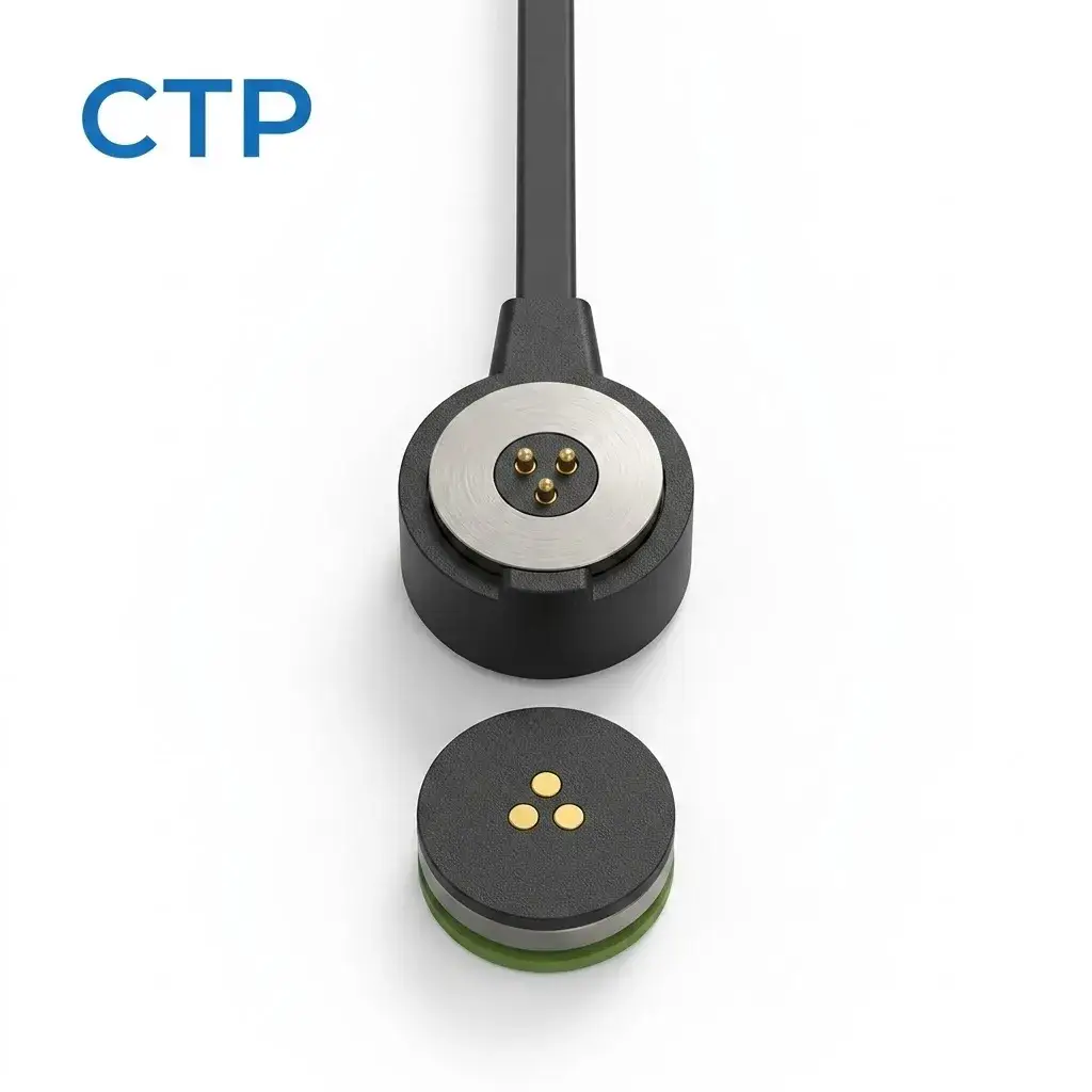
Custom 3-pin round magnetic charging cable with a circular detachable mating interface and three project-defined electrical contacts. The magnetic structure assists capture and retention, while the spring-loaded contacts provide electrical connection and controlled Z-axis compliance. Fast-charging capability, cable construction, pin assignment, current path, opposite-end termination and environmental performance are defined by the approved cable assembly design.
The finished assembly must define the magnetic mating component, internal conductor arrangement, cable construction and the opposite-end connection as one complete electrical system.
Confirm Pin count, contact allocation, magnet arrangement, connector shape, polarity control and mating direction.
Define cable length, conductor count, wire specification, shielding requirements, jacket and flexibility.
Select USB, Type-C, DC plug, bare wire, terminal, PCB connection or another customized termination.
Confirm installation space, outlet direction, strain relief, exposed-contact state and user operation.
This 3-pin round magnetic charging cable combines an attached cable with a circular magnetic mating head and a separate round mating adapter. Three electrical contact positions are arranged within the circular interface for project-defined charging, power, sensing or control functions.
The magnetic structure assists initial capture and retention. Final mechanical seating and alignment should be established by the mating geometry, while the spring-loaded contacts provide electrical connection and controlled Z-axis compliance.
This product should be distinguished from a standalone magnetic connector. The cable, conductor construction, magnetic cable head, mating adapter and opposite-end termination form one complete electrical path.
Cable length, conductor size, cable resistance, strain relief and the opposite-end connector can affect the final charging performance and should therefore be reviewed together with the magnetic contact interface.
The round mating face contains three physical electrical contact positions arranged in a triangular pattern. The presence of three contacts does not determine their electrical functions.
Power, return, identification, sensing, control or other functions should be assigned through the approved customer pin map.
This cable can be developed for fast-charging applications, but the achievable charging performance cannot be established from pin count or connector appearance alone.
Fast-charging capability depends on the power source, opposite-end termination, cable conductor size, cable length, connector termination, pogo contact path, mating interface, device-side PCB and charging-control architecture.
Current capability should be evaluated across the complete electrical path:
Power Source → Opposite-End Connector → Cable Conductors → Cable-to-Head Termination → Spring Contact → Magnetic Mating Interface → Device-Side Contact → Device PCB → Charging Controller → Load.
A previous 5A rating or visible contact diameter is not sufficient to establish an approved continuous current.
For the complete path resistance Rpath, voltage drop follows Vdrop = I × Rpath and resistive power loss follows Ploss = I² × Rpath.
Cable conductor gauge, conductor material, conductor count and cable length contribute directly to total path resistance and voltage drop.
The cable should therefore be specified together with continuous current, peak current, allowable voltage drop, temperature-rise limit and the required opposite-end termination.
Magnetic capture, mechanical seating and valid electrical contact are three related but different interface conditions.
Magnetic attraction alone should not be treated as proof that all three electrical contacts have reached their intended working condition.
A circular connector housing does not automatically establish unrestricted 360-degree electrical mating. If the three contacts have different electrical functions, rotational orientation can affect the pin assignment.
The approved design should define magnet polarity, contact symmetry, mechanical keying, electrical protection or another strategy that prevents an incorrect electrical relationship where required.
The spring-loaded contacts should operate within the working stroke defined by the approved connector drawing. Working stroke is the intended operating compression range and should be distinguished from total available travel.
Final mechanical seating should control the compression condition rather than relying on the pogo contacts as structural stops.
Magnetic performance should be evaluated according to the actual use condition. Capture force, axial separation force and peel behavior can represent different mechanical conditions.
A stronger magnet is not automatically better. The required magnetic retention should be balanced against user separation force, cable pull direction, connector dimensions and device mechanical requirements.
The opposite end of the cable is not visible in the reference image and should not be assumed. USB-A, USB-C, DC plugs, bare wires or another termination should only be specified when confirmed by the cable assembly drawing.
The opposite-end connector and its electrical capability form part of the complete charging path.
The cable-side magnetic head includes a visible cable transition. Final strain-relief geometry, cable bend requirements and pull-force performance should be defined by the approved cable assembly design.
The electrical termination inside the magnetic head should not be used as the only mechanical strain-relief mechanism unless specifically validated for that purpose.
A perimeter ring and a green ring-like feature are visible around the mating components. Their exact function should be confirmed from the mechanical drawing.
The presence of a ring or gasket-like feature does not by itself establish an IP rating. Any waterproof or ingress-protection claim should apply to a defined and tested complete assembly.
This 3-pin round magnetic charging cable architecture can be evaluated for devices that require a detachable cable connection with magnetic capture and three project-defined electrical contacts.
Suitability for fast charging depends on the complete electrical path, cable construction, connector temperature rise, mating condition, device charging architecture and required power level.
CTP can review project-specific requirements for cable length, conductor size, jacket structure, magnetic head dimensions, 3-pin contact arrangement, spring-contact geometry, device-side adapter, magnetic retention, opposite-end termination and cable strain relief.
Final charging performance, mechanical dimensions and environmental requirements should be released through an approved cable assembly drawing and validation plan.
This product is a magnetic charging cable assembly. It includes an attached cable-side magnetic head and a separate round mating component rather than only a standalone magnetic connector.
Three electrical contacts are arranged in a triangular pattern within the round mating interface. Their electrical functions should be defined by the approved customer pin map.
Not automatically. Three contacts provide three physical electrical positions, but their power, return, sensing, identification or control functions are project-defined.
It can be developed for fast-charging applications, but the achievable charging performance depends on the complete cable and device system, including conductor size, cable length, contacts, mating resistance, power source and charging architecture.
Current and voltage capability are project-specific and should be validated across the complete path from the source connector and cable conductors through the magnetic interface to the device load.
The magnets assist capture and retention. Final seating and alignment should be established by the approved circular housing and mechanical interface, while the spring contacts provide electrical connection and axial compliance.
Not necessarily. If the three contacts have different electrical functions, the design must define the rotational mating strategy, contact symmetry, polarity protection or mechanical keying.
A ring-like feature is visible, but its sealing function and any IP rating should only be stated after the complete assembly and validation conditions are confirmed.
Provide the 3-pin map, cable length, conductor requirements, voltage, current, charging requirement, opposite-end termination, magnetic retention, device-side geometry, environment and available 2D or 3D drawings.
If this 3-pin round magnetic cable architecture is close to your device requirement, submit the pin map, cable length, conductor requirements, charging conditions, mating geometry, magnetic requirement and opposite-end termination for engineering review.
Request Custom Quote & Samples | Review Related Magnetic Connector Interfaces
This product page presents a CTP magnetic cable assembly configuration for engineering reference. Final dimensions, electrical ratings, materials, magnet structure, sealing level and reliability targets are not universal values; they are confirmed against the approved drawing, installation condition and model-specific validation plan.
CTP reviews the application and prepares a drawing or specification for approval before sample production. Test scope, acceptance criteria and report format should identify the model, sample status, method, conditions, result and review date.
Yes. Customization can cover geometry, contact layout, materials, cable construction, magnetic structure, sealing and appearance. Feasibility depends on the application and approved specification.
No. Current, voltage, resistance, temperature rise and ingress-protection claims apply only to the identified model and stated test conditions.
Timing is confirmed after the drawing, materials, tooling, sample quantity, validation scope and production requirements have been reviewed.
A reference product image is not enough to define a cable assembly. Confirm the following information before drawing, sampling or quotation review.
The exact project route depends on whether an existing product can be used, modified or requires a new cable assembly design.
Confirm product scope, Pin Map, cable length, termination, quantity and application conditions.
Match magnetic contacts to conductors, source-side wiring and device-side functions.
Confirm dimensions, outlet direction, cable construction and required sample configuration.
Review electrical, mechanical and environmental conditions before production approval.
Submit the magnetic-end structure, electrical functions, cable length, conductor requirements, opposite-end interface, installation space and available drawings for project review.
Review related cable assemblies by contact count, shape, termination and project supply scope.