
Custom Magnetic Pogo Pin Connectors for Wearables & Consumer Electronics
CTP develops compact magnetic pogo pin connectors and magnetic cable assemblies for smartwatches, earbuds, smart rings, AR/VR devices and other portable electronics. Each design is reviewed around available space, charging current, pin assignment, mating cycles, sweat exposure, sealing, magnetic force and the required user experience.
- Compact custom pin layouts
- Charging, detection and selected data
- PCB, FPC and cable mounting
- Custom magnetic holding force
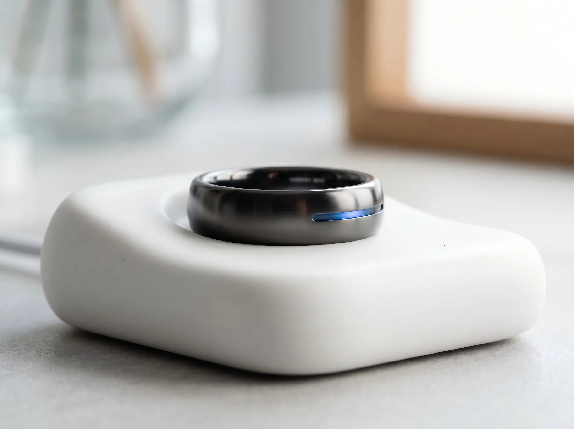
What Is a Magnetic Connector for Wearable Devices?
A wearable-device magnetic connector combines spring-loaded contacts with magnetic self-alignment or controlled release. It can support compact charging, docking, accessory detection and selected signal connections where repeated use and limited enclosure space are important.
The connector should be designed as part of the full device. Pin geometry, spring force, magnet arrangement, housing, cable strain relief, surface materials and environmental exposure all influence final performance.
Six Factors That Shape a Reliable Wearable Connector
Wearable and portable electronics require a balance of compact size, charging performance, durability, environmental resistance and comfort.
Compact Size & Pin Layout
Provide the available height, width, pitch, PCB or FPC position and enclosure tolerance. These inputs determine whether a linear, circular, curved or custom pin arrangement is practical.
Charging Current & Temperature Rise
Continuous current, peak current, voltage, duty cycle, conductor size and allowable temperature rise should be defined before selecting the contact structure and cable.
Mating Cycles & Contact Stability
Expected docking frequency, working compression, spring force, alignment and plating affect durability. The target cycle count should be agreed and verified under the actual mounting condition.
Sweat, Moisture & Corrosion
Artificial sweat, condensation, cleaning agents and daily-wear exposure can affect pins, magnets, adhesives and housing materials. The exact environment should be included in the validation plan.
Magnetic Alignment & Holding Force
Magnet size, grade, arrangement, air gap and mechanical guidance determine alignment and release behavior. The target holding force should be specified in newtons and tested on the final assembly.
Power, Detection & Selected Data
Separate contacts can be assigned to charging, ground, device detection, control or selected data channels. Pin spacing, grounding and cable construction must match the intended interface.
Where Magnetic Pogo Pin Interfaces Can Be Evaluated
These are potential application directions rather than fixed off-the-shelf specifications. Each project requires a separate electrical, mechanical and environmental review.
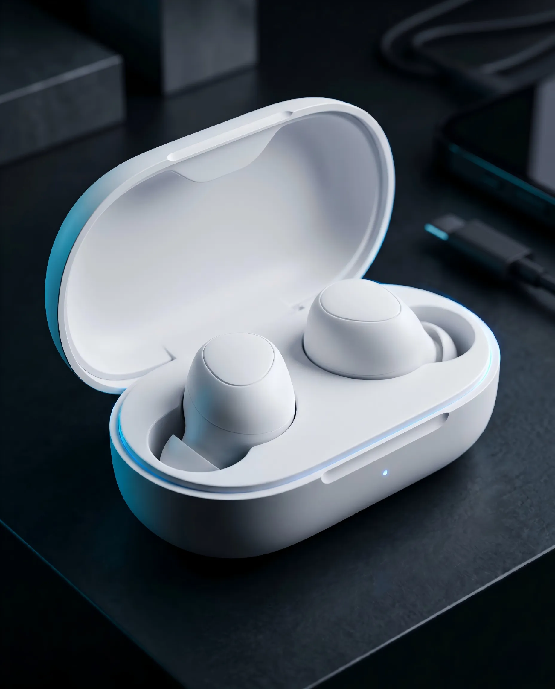
TWS Earbuds & Charging Cases
Compact charging contacts can be developed around case geometry, alignment tolerance, charging current, repeated docking and exposure to sweat or skin oils.
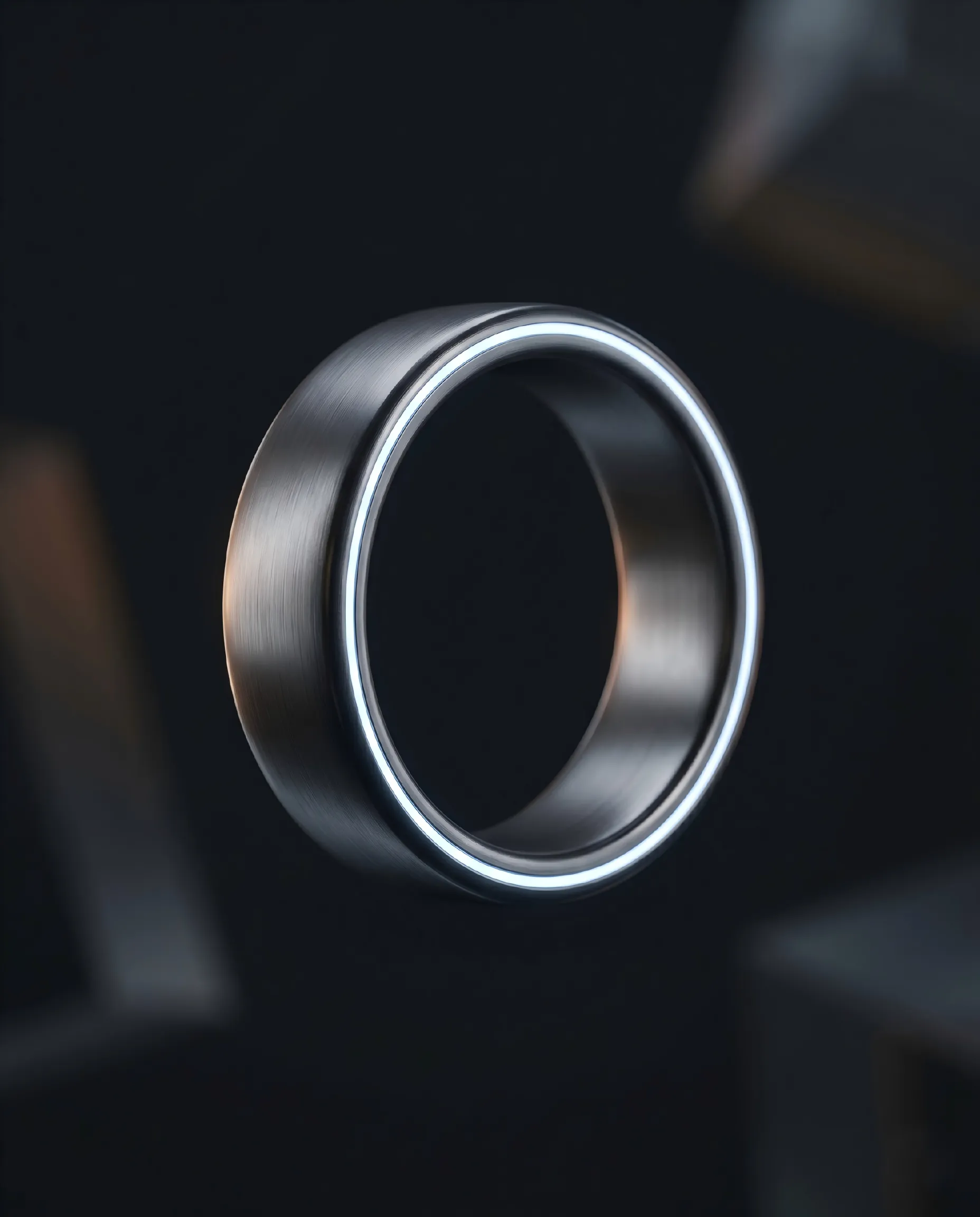
Smart Rings & Miniature Devices
Circular, curved or custom layouts can be evaluated for extremely limited space, subject to the required pitch, insulation, contact force and housing tolerances.
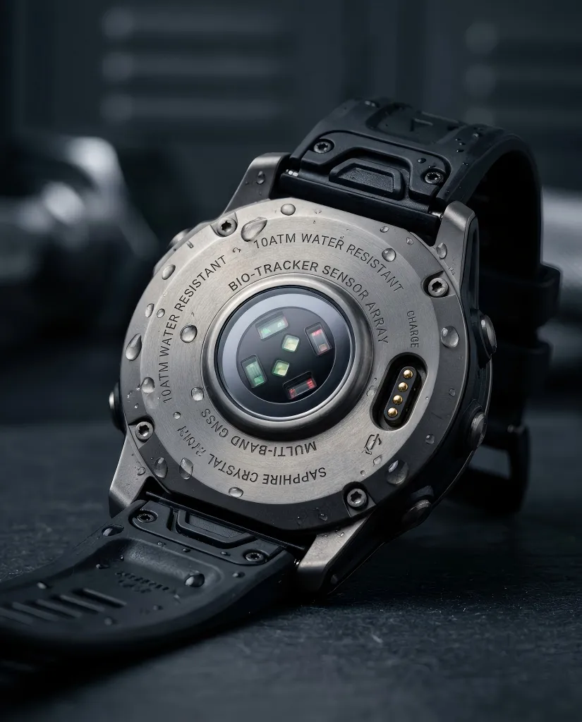
Smartwatches & Fitness Wearables
Magnetic charging and communication interfaces can be developed for daily-wear devices. Sweat, sealing, skin-contact materials and charging temperature must be validated for the complete product.
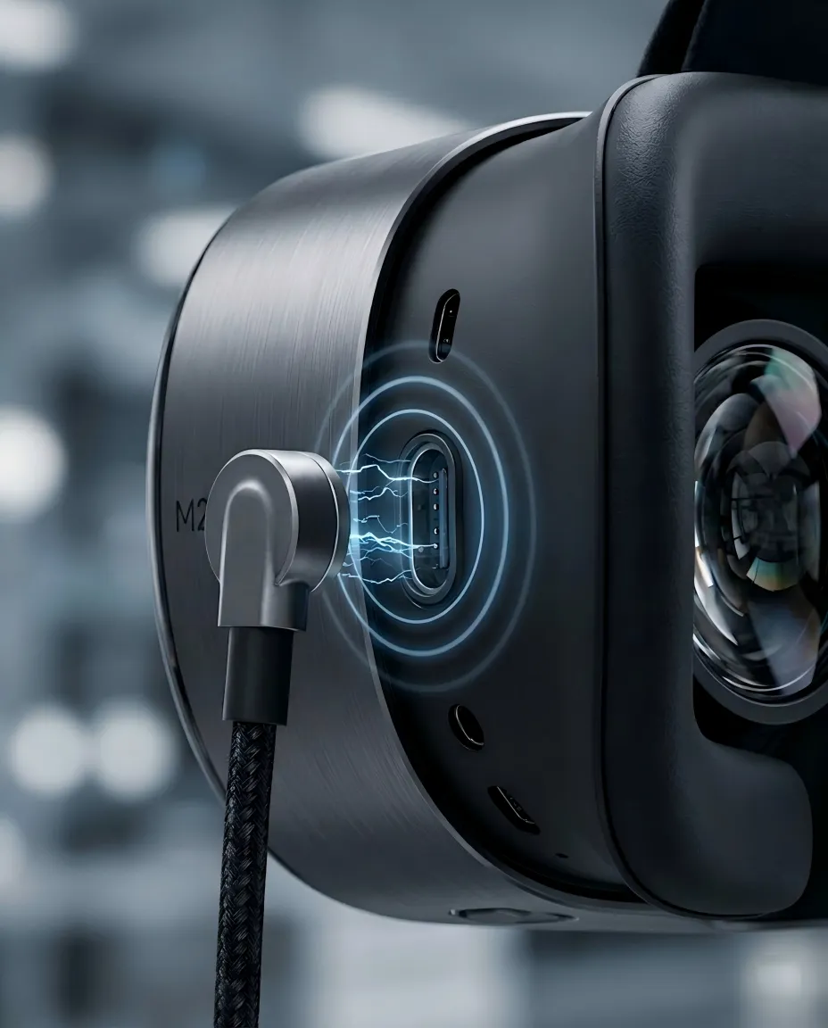
AR/VR Headsets & Accessories
Custom magnetic cable or docking interfaces can support charging, accessory detection and selected signal functions when power, bandwidth, grounding and cable movement requirements are defined.
Images show representative application concepts and do not imply a fixed waterproof rating, biocompatibility result, mating life, charging current or customer-brand endorsement.
Information Needed for a Wearable Connector Review
Providing these inputs early helps determine whether an existing structure can be adapted or a custom connector is required.
| Project input | What to provide | Why it matters |
|---|---|---|
| Electrical load | Voltage, continuous current, peak current, duty cycle and pin assignment | Determines contact structure, conductor size and temperature-rise validation |
| Mechanical envelope | 2D/3D drawing, mating area, PCB/FPC position, pitch and allowable height | Defines pin layout, alignment, housing size and mounting method |
| Magnetic behavior | Target holding force, release direction and acceptable breakaway behavior | Guides magnet layout and mechanical retention design |
| Environment | Sweat, water, humidity, cleaning agents, cosmetics, dust and storage conditions | Influences plating, materials, sealing and validation planning |
| Lifecycle | Expected mating cycles, docking frequency, cable movement and maintenance needs | Supports spring-force selection and durability-test planning |
| Signal requirements | Detection, control or data type, rate, shielding and grounding requirements | Guides pin assignment, spacing and cable construction |
| Project volume | Prototype quantity, pilot quantity, annual volume and target schedule | Supports tooling, process and production-planning decisions |
From Device Requirements to Production Validation
Submit Requirements
Send drawings, pin assignment, electrical load, available space, environmental conditions and expected volume.
Engineering & DFM Review
Review pogo pin compression, magnets, housing, cable, alignment, material exposure and manufacturing feasibility.
Prototype & Project Tests
Produce samples and agree on electrical, durability, force, sweat, cleaning and environmental tests for the intended device.
Pilot & Mass Production
Finalize drawings, inspection criteria, approved materials, process controls and production requirements.
Continue Your Connector Selection
Wearable & Consumer Electronics Connector Questions
Can one magnetic connector carry charging power and data?
Yes. Separate contacts can be assigned to charging, ground, detection, control or selected data channels. The signal type, data rate, shielding and grounding requirements must be reviewed before confirming the design.
Can the connector be made waterproof or sweat resistant?
Water- and sweat-resistant structures can be evaluated, but the final performance depends on the connector, housing, seals, materials, cable outlet and test condition. The complete assembly must be validated for the intended product.
Can skin-contact or nickel-free materials be specified?
Material and plating options can be reviewed against the customer's requirements. Any skin-contact, nickel-release, biocompatibility or allergy-related claim must be supported by the selected material, supplier documentation and final-device validation.
How small can the pin pitch and connector be?
The practical size depends on current, voltage, insulation, spring travel, manufacturing tolerance, assembly process and housing space. Send the 2D or 3D envelope so a suitable layout can be evaluated.
How is mating life determined?
Mating life depends on the pogo pin structure, working compression, spring force, plating, alignment, contamination and device mounting. The target cycle count should be agreed before testing.
What files should I send for an engineering review?
Send a 2D or 3D drawing, installation space, pin assignment, voltage and current, signal requirements, target magnetic force, environmental conditions, expected mating cycles, prototype quantity and annual volume.