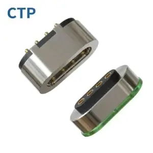
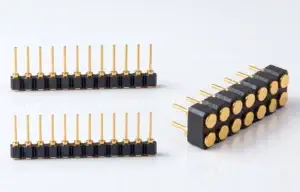
Magnetic pogo pins are most valuable when they are treated as part of a
removable electromechanical interface rather than as individual spring
contacts with magnets added around them. A well-designed interface can
reduce user alignment effort, absorb controlled Z-axis variation, provide
tunable retention and breakaway behavior, support custom power and signal
allocation, simplify the external product surface and create a serviceable
module boundary. Each advantage, however, depends on mechanical, electrical
and manufacturing controls outside the pogo pin itself.
Why Magnetic Pogo Pins Should Be Evaluated as an Interface Architecture
A pogo pin is fundamentally a spring-loaded electrical contact.

A magnetic pogo pin connector adds a separate magnetic system around that
contact architecture to assist mating and retention.

The two functions should remain conceptually separate:


    Pogo Pin
    =
    Electrical Contact + Spring Compliance


while:


    Magnetic System
    =
    Capture + Retention + User Interaction


Mechanical housings, datums and stops then define how the complete assembly
finally mates.

This separation is important because many magnetic connector design
problems occur when the magnet is expected to solve alignment, compression,
retention and electrical reliability at the same time.

A stronger architecture assigns each function to the feature best suited to
control it.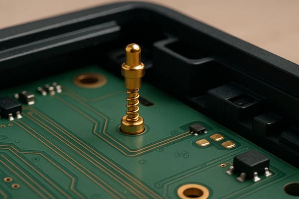
contacts, magnetic capture and mechanical positioning into one
removable product boundary.
Advantage 1: Magnetic Capture Reduces the User’s Alignment Burden
One of the clearest system-level advantages of magnetic pogo pins is that
the user does not always need to manually insert a plug into a deep
receptacle.

As the two product halves approach each other, the magnetic system can help
pull them toward the intended mating region.

This is useful when the interface must support:- blind docking;
- one-handed attachment;
- charging while visibility is limited;
- automatic docking;
- frequently removable modules.
Capture Is Not the Same as Final Alignment
Magnetic attraction can reduce the user's alignment burden, but the final
connector position should normally be established by mechanical geometry.
A controlled mating sequence is:
    Approach
    →
    Magnetic Capture
    →
    Mechanical Guidance
    →
    Final X-Y-Z Seating
    →
    Pogo Pin Compression


Mechanical features may include:- guide walls;
- chamfers;
- locating bosses;
- housing datums;
- anti-rotation geometry;
- mechanical stops.
Multi-Pin Interfaces Need Orientation Control
A connector with multiple electrical functions should also prevent the
wrong contacts from reaching an unintended position.
Possible controls include:
- asymmetric housing geometry;
- mechanical keying;
- magnetic polarity arrangement;
- different target geometry;
- electrical connection detection.
Physical attraction alone should not be treated as proof that the connector
is correctly seated.
Advantage 2: Spring Compliance Creates a Controlled Z-Axis Tolerance Window
A rigid contact interface requires the two conductive surfaces to meet at a
relatively precise installed height.

A pogo pin introduces controlled axial movement.
A simplified relationship is:
S = Hfree - Hseatedwhere:
- S = actual pogo pin compression;
- Hfree = installed free height;
- Hseated = final installed height after mechanical seating.
This gives the connector designer a defined range of Z-axis compliance.This Can Absorb Controlled Assembly Variation
Final compression can vary because of:- PCB thickness;
- solder height;
- connector-height tolerance;
- housing dimensions;
- target height;
- module flatness;
- assembly tolerance.
A pogo pin can accommodate part of that controlled variation while
maintaining electrical contact.
But Working Stroke Does Not Replace the Tolerance Stack
Engineers should still calculate:


    Minimum Compression
    /
    Nominal Compression
    /
    Maximum Compression


across the complete assembled tolerance window.

The goal is to make sure every production unit remains inside the approved
operating range.
Total Travel Is Not the Normal Working Stroke
A pogo pin can often physically travel beyond its normal operating
compression.

That extra travel should not automatically become the product's mechanical
stop.

Product geometry should establish the final seating position so that the
spring contact is used for electrical compliance rather than as the primary
structural stop.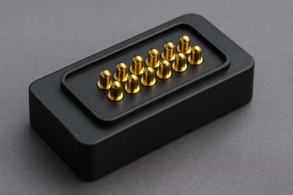
the final stroke still depends on the complete PCB, housing and target
tolerance stack.
Advantage 3: Retention and Breakaway Can Be Designed as Part of the User Experience
A conventional locking connector is normally designed to remain attached
until the latch, thread or lock is deliberately released.

A magnetic pogo pin interface can be designed around a different user
interaction:


    stay connected during normal use, but separate when a defined external
    load is applied.


This can be useful for:- removable charging cables;
- tabletop devices;
- wearable charging interfaces;
- portable instruments;
- docking modules.
Capture, Retention and Breakaway Are Three Different Requirements
| Mechanical State | Engineering Question |
|---|---|
| Capture | How should the connector behave during approach? |
| Seated Retention | What loads must it tolerate during normal use? |
| Breakaway | Under what load and direction should it separate? |
Axial pull and peel separation can also produce very different behavior.The Magnet Must Work Against the Complete Mechanical Load
A simplified force budget can be considered as:
    Available Retention
    >
    Pogo Spring Reaction
    +
    Seal Reaction
    +
    Cable / Module Load
    +
    Expected Dynamic Disturbance


This is a design concept rather than a universal equation for every
connector.

The important principle is that magnet force should be evaluated against
the complete mechanical system.
Stronger Magnets Are Not Automatically Better
Excessive attraction can create:- uncomfortable removal force;
- higher closing impact;
- more housing load;
- greater lateral sliding during capture;
- increased attraction of ferromagnetic debris.
Magnetic behavior should therefore be tuned to the product rather than
maximized.
Advantage 4: The External Interface Can Be Shallower Than Many Plug-and-Receptacle Designs
Traditional plug-and-receptacle connectors often require:- an insertion path;
- a receptacle cavity;
- shell geometry;
- retention features;
- access space around the plug.
Magnetic pogo pin contacts can instead be arranged against a relatively
shallow or flush mating surface.

This creates additional enclosure freedom when product depth is limited.
Low Z Height Does Not Mean Zero Packaging Cost
The complete 3D envelope can still include:- pogo pin body height;
- recommended working stroke;
- magnet dimensions;
- housing wall;
- PCB routing area;
- FPC or cable bend radius;
- mechanical guide features.
A low-profile connector can save vertical space while consuming additional
X-Y area.
Pitch Should Follow the Complete Electrical and Manufacturing Requirement
Reducing contact pitch can make the interface more compact, but it can also
affect:- PCB routing;
- electrical spacing;
- target-pad size;
- manufacturing tolerance;
- alignment sensitivity;
- signal interaction.
The correct metric is therefore the complete connector envelope, not only
overall height.
Advantage 5: A Custom Pin Map Can Turn the Connector into a Module Boundary
One of the strongest architectural advantages of a custom magnetic pogo pin
connector is the ability to decide what functions cross the removable
boundary.
A Pin Map may include:
- power;
- power return;
- connection detection;
- module identification;
- control signals;
- selected data signals.
This allows the connector to become part of the product architecture rather
than only a charging interface.
Pin Count Should Follow Function
A stronger design flow is:
    Product Functions
    →
    Required Electrical Paths
    →
    Pin Map
    →
    Contact Count
    →
    Connector Geometry


This is preferable to selecting a pin count first and then trying to fit all
system functions into the available contacts.
Current Capability Comes from the Complete Power Path
A simplified path is:
    Source
    →
    PCB / Cable
    →
    Termination
    →
    Pogo Pin
    →
    Contact Interface
    →
    Target
    →
    Load
Voltage drop follows:
Vdrop = I × Rpathwhile resistive loss follows:
Ploss = I² × Rpath

Current rating should therefore be validated from complete-path resistance
and temperature rise rather than from contact diameter alone.
Parallel Power Contacts Require Current-Sharing Validation
Multiple contacts can be connected in parallel, but current may not divide
equally because of:- contact-resistance variation;
- stroke variation;
- target flatness;
- PCB routing;
- module tilt;
- termination resistance.
Pin Count Does Not Define Data Performance
Signal performance can depend on:- signal-to-return allocation;
- contact pitch;
- contact geometry;
- PCB transition;
- reference-plane continuity;
- FPC or cable construction;
- complete channel length.
A multi-pin connector should therefore not be described as a particular
high-speed interface without the appropriate channel design and validation.
Advantage 6: A Flat Target Surface Can Simplify the External Service Boundary
A removable connector is not only an electrical interface.

It is also a physical boundary between the user or environment and the
electronics inside the product.

A relatively flat magnetic contact surface can provide advantages such as:- fewer deep cavities;
- easier visual inspection;
- simpler wiping or cleaning;
- greater freedom in enclosure styling;
- replaceable cable-side contact structures.
Flat Does Not Automatically Mean Waterproof
Environmental protection still depends on the complete boundary:


    External Contact
    →
    Feedthrough
    →
    Connector Housing
    →
    Housing Joint
    →
    PCB / FPC / Wire
    →
    Protected Electronics


Possible sealing elements can include:- insert molding;
- gaskets;
- potting;
- overmolding;
- sealed housing joints.
A specific IP rating should only be associated with the defined and tested
connector or product configuration.
The Unmated State Deserves Separate Review
When the cable or removable module is disconnected, the external targets may
remain exposed to:- water;
- sweat;
- dust;
- cleaning fluid;
- skin oils;
- foreign conductive objects.
Enclosure sealing and exposed-contact electrical behavior are therefore two
different engineering questions.
but the complete environmental boundary still requires dedicated
engineering and validation.
Advantage 7: The Connector Can Be Designed as a Replaceable Module
Magnetic pogo pin interfaces can be integrated at several levels.Manufacturing options include:
- individual PCB-mounted pogo pins;
- multi-pin plastic housings;
- integrated magnetic connector modules;
- FPC-terminated modules;
- wire-terminated assemblies;
- magnetic cable assemblies.
This flexibility allows the engineering team to decide where assembly
complexity and wear should be located.
Choose Which Side Should Become the Serviceable Wear Component
In a frequently used product, the device-side PCB may be expensive to
replace while the cable or docking plate is relatively inexpensive.

The interface can therefore be designed so that the easier-to-replace side
absorbs more of the expected service wear.

Possible replaceable components include:- charging cable head;
- docking target;
- contact module;
- removable PCB subassembly.
Integrated Modules Can Simplify Final Assembly
A connector module can combine:- contacts;
- magnets;
- housing;
- FPC;
- wires;
- cable termination.
This can reduce the number of alignment operations required on the final
product assembly line.

However, module integration only becomes a manufacturing advantage when the
interface CTQs are clearly controlled.
Production CTQs May Include
| CTQ Area | Possible Control |
|---|---|
| Contact Geometry | Pitch, installed height and position |
| Spring Interface | Working stroke and force at defined compression |
| Magnetic System | Polarity, position and defined retention behavior |
| Mating Target | Geometry, flatness and surface requirement |
| Electrical | Resistance or voltage drop under defined conditions |
| Termination | PCB, FPC, wire or cable assembly requirement |
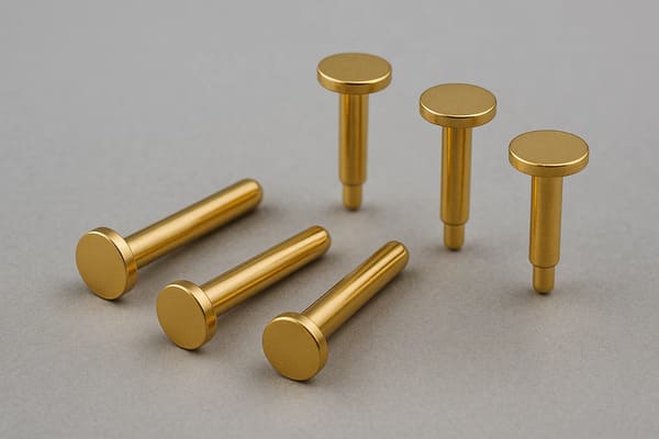
contact position, stroke, magnetic behavior and termination are
controlled as one interface.
Every Advantage Requires an Engineering Control
Magnetic pogo pin advantages should not be treated as automatic component
properties.| System Advantage | Required Engineering Control |
|---|---|
| Blind Mating | Mechanical guides, keying and final datums |
| Z-Axis Compliance | Working-stroke and tolerance-stack analysis |
| Breakaway | Capture, retention and separation-force definition |
| Compact External Surface | Complete 3D connector-envelope review |
| Flexible Pin Map | Power-path, return-path and signal validation |
| Serviceable External Interface | Environmental, contamination and exposed-state design |
| Integrated Module | CTQs, production inspection and revision control |
This relationship is important:


    Advantage
    +
    Engineering Control
    =
    Useful Product Function


Without the corresponding control, the same feature can become a source of
variation or failure.
When Do These Advantages Matter Most?
| Product Requirement | Why Magnetic Pogo Pins May Be Useful |
|---|---|
| Frequent Removable Connection | Spring contacts and a shallow mating interface support repeated docking |
| Blind or One-Handed Mating | Magnetic capture reduces user alignment effort |
| Controlled Z Variation | Pogo pin stroke provides axial compliance |
| Breakaway Requirement | Magnetic retention can be designed to allow separation |
| Custom Module Boundary | Pin Map can combine power, detection and selected signals |
| Serviceable External Surface | Flat targets and replaceable mating components can simplify maintenance |
| Custom Assembly Integration | Contacts, magnets, housings and terminations can be integrated into modules |
When Magnetic Pogo Pins May Not Be the Best Architecture
These advantages do not mean magnetic pogo pins should replace every
connector.
A different architecture may be better when:
- a strong positive mechanical lock is required;
- the connection should remain permanent;
- third-party standardized interoperability is required;
- very high contact density dominates the design;
- a standardized high-speed connector already meets the requirement;
- magnetic fields create unacceptable product constraints;
- metallic debris cannot be adequately managed;
- the additional magnetic system provides little product-level value.
Connector selection should therefore begin with the product interface
requirement rather than with a preference for one connector technology.
A Practical Magnetic Pogo Pin Interface Selection Workflow
Before starting a custom connector design, work through the following
sequence:


    Does the Interface Need to Be Removable?
    ↓
    Is Blind or Low-Effort Mating Valuable?
    ↓
    Is Z-Axis Compliance Required?
    ↓
    Is Controlled Breakaway Useful?
    ↓
    What Functions Cross the Interface?
    ↓
    What Is the Environmental Boundary?
    ↓
    Which Side Should Be Serviceable?
    ↓
    Define the Connector Architecture
Information Required Before Starting a Custom Design
| Project Input | Information to Provide |
|---|---|
| Product Architecture | Which two assemblies need to connect? |
| Available Space | X, Y and Z connector envelope |
| Pin Map | Power, return, detection, identification and signal functions |
| Electrical Conditions | Voltage, continuous current, peak current and duty cycle |
| Signal Requirement | Control or communication channel requirements |
| Working Stroke | Available minimum, nominal and maximum compression |
| Mating Tolerance | X-Y-Z and angular variation |
| Magnetic Behavior | Capture, retention and separation requirements |
| Environment | Temperature, moisture, sweat, salt, dust, oil or chemicals |
| Lifecycle | Expected mating profile and service requirement |
| Termination | PCB, FPC, wire or cable architecture |
| Project Files | 2D drawing, 3D assembly, PCB layout or enclosure model |
Frequently Asked Questions
What are the main advantages of magnetic pogo pins?
Their main system-level advantages can include magnetic capture for easier
mating, controlled Z-axis compliance, tunable breakaway behavior, shallow
external geometry, flexible Pin Maps, serviceable external surfaces and
modular connector integration.
Are magnetic pogo pins the same as normal pogo pins?
No. A pogo pin is a spring-loaded electrical contact. A magnetic pogo pin
connector combines spring contacts with a separate magnetic capture or
retention system.
Do magnets automatically align pogo pins accurately?
No. Magnets can assist capture, but mechanical datums, guides and stops
should normally define the final connector position.
What is pogo pin working stroke?
Working stroke is the intended amount of pogo pin compression in the final
assembled interface. It should be evaluated across the complete product
tolerance stack rather than from nominal dimensions alone.
Are stronger magnets better for a magnetic pogo pin connector?
Not automatically. Stronger attraction may increase retention but can also
increase separation effort, closing impact, housing load and metallic-debris
attraction.
Can magnetic pogo pins be used for high current?
They can be designed as part of higher-current interfaces, but capability
depends on complete-path resistance, working stroke, target, termination,
PCB or cable design, duty cycle and temperature rise.
Can magnetic pogo pins transmit data?
They can carry selected signals, but pin count alone does not establish
bandwidth. Signal and return allocation, contact geometry, PCB transitions,
cable construction and the complete channel should be validated.
Are magnetic pogo pin connectors waterproof?
Not automatically. A magnetic pogo pin interface can be integrated into a
sealed product, but the actual ingress protection depends on the complete
housing, feedthrough, gasket, potting and termination architecture.
Do magnetic pogo pins reduce connector wear?
They can reduce the long insertion path used by some plug-and-receptacle
connectors, but the pogo tip and mating target still experience contact wear
and can be affected by misalignment, contamination and repeated mating.
Can magnetic pogo pins provide breakaway protection?
A magnetic interface can be designed to separate under a defined load, but
the required behavior depends on pull direction, magnet layout, spring
reaction, cable load and product geometry.
When should magnetic pogo pins be considered?
They are particularly worth evaluating when a product needs a frequently
removable interface, blind mating, Z-axis compliance, controlled breakaway,
a custom Pin Map or a serviceable external contact surface.
When should I use a conventional connector instead?
A conventional connector may be preferable when positive locking,
permanent mating, standardized interoperability, very high contact density
or an established high-speed interface is the dominant requirement.
Request a Magnetic Pogo Pin Interface Engineering Review
Explore

    CTP custom magnetic connector solutions

for removable charging, docking and modular product interfaces.

Review

    pogo pin and spring-contact connector solutions

for different contact layouts and mounting structures.

Learn more about CTP engineering and manufacturing capabilities on the

    About Us page
. Submit your connector envelope, Pin Map, working stroke, voltage,
current, mating tolerance, retention requirements, environmental
conditions and available 2D or 3D files to CTP for an engineering
review.
The interface can be reviewed as a complete mechanical and electrical
boundary before the connector geometry is frozen.
Final electrical performance, magnetic behavior, environmental
protection, lifecycle and manufacturing tolerance should be confirmed
against the approved connector design and project-specific validation
conditions.
CTP ENGINEERING PATHS
Choose the right path for your project
Move from application requirements to a connector pair, a data-capable cable assembly, or a charging cable configuration. Final specifications are confirmed against an approved drawing and project validation plan.
Magnetic Connectors
Connector geometry, pin layout, mechanical integration and OEM/ODM review.
Engineering overview → 02Magnetic Data Cables
Power and signal allocation, cable exit, interface selection and assembly review.
Cable engineering → 03Magnetic Charging Cables
Browse the complete cable catalog and shortlist a starting structure for customization.
View cable catalog →