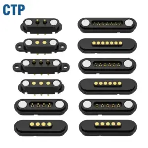
A magnetic connector does not need to remain a simple power interface.
Once the product boundary has reliable mechanical seating and spring-loaded
electrical contact, engineers can expand the interface with connection
detection, module identification, controlled power enable, service access,
selected signals and reusable accessory definitions. The important step is
to treat the connector as an interface contract rather than simply adding
more pins.
Magnetic Connectors Can Be More Than Charging Contacts
Many magnetic connector projects begin with a simple requirement:


    “We need two contacts to charge the device.”


That may be all the product needs.

But once a removable magnetic interface already exists between two
assemblies, the engineering team has created something more valuable than
two conductive pads.

It has created a reusable product boundary.
That boundary can potentially carry:
- charging power;
- power return;
- connection detection;
- accessory identification;
- diagnostic functions;
- control signals;
- selected communication channels.
This does not mean every magnetic connector should contain more contacts.

It means engineers should ask whether the existing interface can support
additional product functions before creating another external connector.
A useful evolution is:
    Simple Charging Port
    →
    Detected Charging Interface
    →
    Identified Accessory Interface
    →
    Controlled Modular Interface
    →
    Reusable Product Platform
Start with the Interface Contract
Expanding a connector successfully requires more than adding pins.

The two sides of the interface should share a controlled definition of:- mechanical geometry;
- mating orientation;
- final seating position;
- working stroke;
- Pin Map;
- voltage architecture;
- allowed current;
- connection-state logic;
- identification behavior;
- environmental exposure.
This collection of requirements can be treated as an
interface contract.

The more functions that cross the magnetic boundary, the more important
that interface contract becomes.
Expansion 1: Add Connection Detection
The simplest intelligent extension beyond basic charging is often
connection detection.

A two-contact charging interface may only tell the system that voltage is
present.

A dedicated detection path can allow the system to distinguish:


    No Accessory
    ↓
    Accessory Approaching
    ↓
    Connector Seated
    ↓
    Valid Connection
Why Detection Matters in a Magnetic Interface
Magnetic attraction can begin before the connector reaches its final seated
condition.

Therefore:


    Magnetic Attachment
    ≠
    Mechanical Seating
    ≠
    Valid Electrical Connection


A dedicated detection contact can help the controller determine whether the
interface has reached a usable state.
Detection Can Support More Than Charging
Connection detection can be useful for:- waking the product;
- starting a handshake;
- enabling another subsystem;
- logging dock events;
- preventing operation when the interface is incomplete.
The detection method should follow the actual electrical and mechanical
architecture.
Expansion 2: Add Module or Accessory Identification
Once the product knows that something is attached, the next question can be:


    “What exactly is attached?”


This allows the magnetic interface to evolve from:


    Connector Present
to:
Known Accessory Present
Why Identification Can Be Useful
One host product may eventually need to support:- a basic charger;
- a desktop dock;
- a service fixture;
- a sensor module;
- a battery module;
- a future accessory.
If these accessories share a common mechanical interface, identification can
help the host apply the correct system behavior.
Physical Compatibility Is Not Electrical Compatibility
Two modules may physically attach to the same magnetic connector while
requiring different:- voltages;
- current limits;
- signal assignments;
- software behavior;
- power-up sequences.
Therefore:


    Same magnetic geometry does not automatically mean interchangeable
    accessories.


Identification becomes increasingly valuable as the accessory ecosystem
grows.
Expansion 3: Separate Attachment from Main Power Enable
A simple magnetic charger can energize contacts as soon as the interface is
attached.

A more controlled architecture can instead separate:


    Mechanical Attachment
    ↓
    Electrical Detection
    ↓
    Accessory Validation
    ↓
    Main Power Enable
Why This Matters
The connector can pass through intermediate states such as:- one edge touching first;
- only some contacts engaged;
- incorrect orientation;
- debris preventing final seating;
- wet exposed contacts.
Controlled power sequencing can prevent the system from treating every
magnetic attachment event as a valid full-power condition.
The Connector Does Not Perform the Power Control by Itself
A detection or pilot contact can provide state information.

The controller, switch, charger IC or other system electronics must perform
the required power-enable action.

A contact becoming active earlier than another contact does not, by itself,
suppress arcing or supports safe power transfer.
Expansion 4: Add a Service and Diagnostic Path
A magnetic interface that is already accessible from the outside of the
product can sometimes serve another function:


    temporary service access.
Depending on the product architecture, this can support:
- factory programming;
- firmware recovery;
- diagnostic communication;
- calibration;
- service testing;
- production verification.
This Can Reduce the Need for a Second Service Connector
Instead of creating:


    Charging Connector
    +
    Factory Test Connector
    +
    Service Connector


some products may be able to use:


    One Controlled Magnetic Interface
    ↓
    Charging
    +
    Factory Fixture
    +
    Service Tool


Whether this is practical depends on the Pin Map, system logic, production
process and service requirements.
Service Functions Should Not Accidentally Become User Functions
If diagnostic contacts are externally accessible, the product architecture
should define:- when the interface is active;
- which accessory is allowed to access it;
- what electrical state exists when no service tool is attached;
- how incorrect attachment is handled.
Expansion 5: Add Selected Signal Functions
Multi-pin magnetic connectors can support more than DC power.

Selected contacts may be assigned to:- control lines;
- low-speed communication;
- device detection;
- accessory status;
- other project-specific signals.
But adding signal pins is not the same as creating a validated data
interface.
Pin Count Does Not Define Data Capability
Signal performance can depend on:- signal-to-return allocation;
- contact geometry;
- contact spacing;
- PCB transitions;
- reference-path continuity;
- FPC or cable architecture;
- complete channel length.
Therefore:


    More Contacts
    ≠
    More Bandwidth
Start with the Required Signal
The correct development flow is:


    Required Communication Function
    →
    Electrical Channel Requirement
    →
    Pin Map
    →
    Contact Geometry
    →
    Channel Validation


This is more reliable than selecting a high pin count first and assigning
signal names afterward.
Expansion 6: Turn One Connector into an Accessory Ecosystem
Once mechanical geometry, Pin Map and system behavior are controlled, the
same magnetic interface can potentially support more than one accessory.
For example:
    HOST DEVICE
    ↓
    ONE MAGNETIC INTERFACE
    ↓
    Charging Cable
    Desktop Dock
    Sensor Module
    Service Fixture
    Factory Fixture
    Future Accessory
This Is Where Connector Design Becomes Product Architecture
The connector is no longer only a component.

It becomes a reusable boundary between the core product and external
modules.

This can allow product teams to develop:- multiple accessory SKUs;
- different charging formats;
- service tools;
- future modules;
- regional or customer-specific accessories.
Compatibility Must Be Controlled
A shared connector should define:
- mechanical mating geometry;
- magnetic polarity;
- Pin Map;
- voltage range;
- allowed current;
- identification rules;
- connection-state behavior;
- revision compatibility.
Without this control, an accessory ecosystem can create incompatibility
rather than modularity.
Expansion 7: Standardize the Interface Across a Product Platform
The highest level of interface expansion is to move from:


    One Connector for One Product
to:
    One Controlled Interface
    Across Multiple Product Generations


This can allow a company to reuse parts of the interface architecture
across:- different product sizes;
- multiple device generations;
- shared charging docks;
- common factory fixtures;
- service equipment;
- accessory families.
The Interface Contract Becomes More Important as Reuse Increases
Once several products depend on the same interface, uncontrolled changes
can have larger consequences.

Revision control may need to address:- contact geometry;
- Pin Map;
- housing datum;
- magnet polarity;
- electrical limits;
- identification behavior;
- mechanical compatibility.
Backward Compatibility Should Be Deliberate
A new product physically fitting an old charger does not prove backward
compatibility.

Compatibility should be confirmed across the complete:


    Mechanical
    +
    Electrical
    +
    System Logic


interface.
From 2 Pins to a Modular Interface: A Practical Evolution
| Interface Stage | Possible Functions | Main Engineering Question |
|---|---|---|
| Stage 1 | Power + Return | Can the interface charge reliably? |
| Stage 2 | Power + Return + Detection | Can the system distinguish attached from detached? |
| Stage 3 | Detection + Identification | Can the host determine which accessory is attached? |
| Stage 4 | Controlled Power Enable | Should full power wait until the connection is validated? |
| Stage 5 | Diagnostic / Service Functions | Can the same interface support production and service? |
| Stage 6 | Selected Signals | Does the required channel meet electrical performance? |
| Stage 7 | Accessory / Platform Interface | Can multiple products and modules share one controlled boundary? |
Do Not Add Pins Without a System Reason
Interface expansion creates capability, but it also creates cost and
complexity.
Adding contacts can increase:
- connector size;
- spring reaction force;
- magnetic retention requirements;
- PCB routing complexity;
- alignment sensitivity;
- partial-mating complexity;
- test requirements;
- software interface states.
Therefore:


    Every new pin should have a defined system function.
A better flow is:
    New Product Function
    →
    New Electrical Requirement
    →
    Pin Map Review
    →
    Mechanical / Electrical Impact
    →
    Add Contact Only If Needed
Interface Expansion Changes the Mechanical Design Too
Adding functions does not only affect electronics.For example:
    More Contacts
    →
    More Total Spring Reaction
    →
    Different Retention Requirement
    →
    Different Magnet / Housing Architecture
or:
    Smaller Contact Pitch
    →
    Tighter Landing Tolerance
    →
    More Demanding Mechanical Datum Control
or:
    More Power Paths
    →
    More PCB Copper
    →
    More Routing Area
    →
    Different Connector Package


Mechanical, electrical and magnetic design therefore remain coupled as the
interface expands.
Power Capability Should Still Be Validated as a Complete Path
Even a sophisticated multi-function magnetic interface still follows the
same basic conductive path:


    Source
    →
    PCB / Cable
    →
    Termination
    →
    Pogo Contact
    →
    Contact Interface
    →
    Target
    →
    Device PCB
    →
    Load
A simplified path model is:
    Rpath =
    Rsource +
    Rtermination +
    Rpogo +
    Rinterface +
    Rtarget +
    Rload
with:
Vdrop = I × Rpathand:
Ploss = I² × Rpath

Adding identification or signal contacts does not change the requirement to
validate power paths using the complete electrical and thermal system.
Partial Mating Becomes More Important as the Interface Becomes Smarter
A simple two-contact charger has relatively few electrical states.

A multi-function interface can have many more.
For example:
    No Connection
    ↓
    Magnetic Capture
    ↓
    Detect Contact Engaged
    ↓
    Identification Contact Engaged
    ↓
    Power Contacts Fully Seated
    ↓
    Validated Accessory
    ↓
    Full Operation


Engineers should define what the system is allowed to do at every relevant
stage.

This is particularly important where:- some contacts are longer than others;
- power contacts operate in parallel;
- wet exposed contacts are possible;
- multiple accessory types exist;
- different modules use different power states.
When Interface Expansion Does Not Make Sense
More capability does not automatically create a better product.

A simple charging connector may remain the better architecture when:- only charging is required;
- accessory identification creates no user value;
- service access already exists elsewhere;
- product space is extremely constrained;
- additional pins create unnecessary routing complexity;
- standard external interoperability is more important than a proprietary modular interface.
The interface should expand only when the additional function creates a
measurable product, manufacturing or service benefit.
Questions to Ask Before Expanding a Magnetic Interface
| Architecture Area | Question |
|---|---|
| Product Function | What new capability requires another contact or interface state? |
| Mechanical | Will additional contacts change package size, spring reaction or alignment? |
| Pin Map | What function is assigned to every contact? |
| Detection | How does the host know the interface is fully seated? |
| Identification | Does the host need to know which accessory is connected? |
| Power | When is main power allowed to turn on? |
| Signals | What electrical channel performance is actually required? |
| Service | Can the same interface support diagnostics or production fixtures? |
| Platform | Should future products reuse the interface? |
| Compatibility | How will revision and accessory compatibility be controlled? |
A Practical Magnetic Interface Expansion Workflow
A useful development sequence is:


    Define Existing Interface
    →
    Identify New Product Function
    →
    Update Interface Contract
    →
    Update Pin Map
    →
    Review Mechanical Impact
    →
    Review Power / Signal Architecture
    →
    Define Connection States
    →
    Prototype
    →
    Validate
    →
    Freeze Revision
Frequently Asked Questions
Can magnetic connectors do more than charging?
Yes. Depending on the architecture, additional contacts can support
connection detection, accessory identification, diagnostics, control
signals and selected communication functions.
How many pins should a magnetic connector have?
There is no universal number. Contact count should follow the required
functions in the Pin Map rather than being selected first.
Why add a detection pin to a magnetic connector?
A detection contact can help the system distinguish magnetic attachment from
a fully seated and electrically valid connection.
Can a magnetic connector identify different accessories?
It can if the interface includes an appropriate identification method and
the host electronics are designed to interpret it.
Should power turn on immediately when a magnetic connector attaches?
Not necessarily. Some systems may benefit from confirming seating or
accessory identity before enabling the main power path.
Can a magnetic charging connector also be used for factory testing?
Potentially. If the Pin Map and system architecture support it, the same
interface may be used for charging, programming, diagnostics or production
fixtures.
Can magnetic pogo pin connectors carry communication signals?
Selected signals can be supported, but data capability depends on the
complete channel, including contact geometry, return paths, PCB transitions
and cable or FPC construction.
Does adding more pins increase current capability?
Not automatically. Multiple contacts can be used in parallel, but current
sharing and complete-path temperature rise must still be validated.
Can one magnetic connector support multiple accessories?
Yes, if mechanical geometry, Pin Map, voltage, current limits,
identification and connection-state logic are controlled as one interface
specification.
What is a magnetic connector platform interface?
It is a controlled mechanical and electrical boundary reused across several
products, accessories, docks or service tools rather than being designed for
only one connection.
What is the biggest risk when expanding a magnetic interface?
Complexity can grow faster than the product value. Additional contacts,
electrical states and accessory types increase mechanical, electrical,
software and validation requirements.
When should a magnetic interface remain a simple charging connector?
When the product only requires power and return, additional detection,
identification or communication contacts may add cost and complexity without
meaningful system benefit.
Request a Magnetic Interface Architecture Review
Explore

    CTP custom magnetic connector solutions

for charging, docking and modular hardware interfaces.

Review

    pogo pin and spring-contact connector solutions

for project-specific contact layouts and mounting architectures.

Learn more about CTP engineering and manufacturing capabilities on the

    About Us page
. Submit your current connector architecture, Pin Map, voltage, current,
available X-Y-Z space, planned accessory functions and available 2D or
3D files to CTP for an engineering review.
The interface can be reviewed from a system level to determine which
functions should remain inside the host product and which functions are
worth moving across the removable magnetic boundary.
Final electrical performance, signal capability, mechanical
compatibility, environmental behavior and production requirements
should be confirmed against the approved interface revision and
project-specific validation conditions.
CTP ENGINEERING PATHS
Choose the right path for your project
Move from application requirements to a connector pair, a data-capable cable assembly, or a charging cable configuration. Final specifications are confirmed against an approved drawing and project validation plan.
Magnetic Connectors
Connector geometry, pin layout, mechanical integration and OEM/ODM review.
Engineering overview → 02Magnetic Data Cables
Power and signal allocation, cable exit, interface selection and assembly review.
Cable engineering → 03Magnetic Charging Cables
Browse the complete cable catalog and shortlist a starting structure for customization.
View cable catalog →