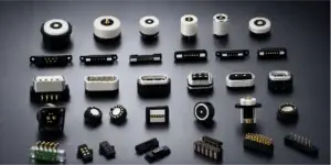
Magnetic pogo pin connectors can support modular scientific instruments
by combining spring-loaded electrical contacts with magnet-assisted
attachment. They can provide removable paths for power, detection,
identification, control and project-specific signals, but the connector
alone does not establish hot-swap capability, measurement accuracy, EMI
immunity or protocol performance. Successful integration requires a defined
Pin Map, controlled pogo pin working stroke, mechanical alignment, grounding
and shielding strategy, electrical sequencing and complete instrument-level
validation.
Why Modularity Becomes an Interconnect Problem
Modern scientific instruments increasingly combine multiple functional
subsystems: sensor heads, optical modules, detector assemblies, sample
handling components, calibration fixtures, control electronics and
replaceable accessories.
Making these subsystems removable can simplify service, configuration and
product-family development. However, once a module becomes detachable, the
electrical interface becomes part of the system architecture.
Engineers must determine how the module receives power, how it is identified,
how signals are referenced, how the two mechanical halves align and what
happens electrically before the module is completely seated.
A magnetic pogo pin connector can be one possible interface architecture.
Magnets can assist attachment while spring-loaded contacts provide compliant
electrical paths between the removable module and the host instrument.What a Magnetic Pogo Pin Interface Can and Cannot Do
| Engineering Requirement | Possible Connector Contribution | What Still Requires System Design |
|---|---|---|
| Removable Module | Provides reusable electrical contact between two mating assemblies | Module structure, service procedure and product architecture |
| Blind Mating | Magnets can assist initial capture | Final mechanical alignment and allowable mating offset |
| Power Transfer | Provides conductive contact paths | Current rating, protection, sequencing and thermal design |
| Signal Connection | Provides project-specific conductive paths | Protocol, routing, reference paths and signal-integrity validation |
| Module Detection | A dedicated contact can be assigned to detection or identification | Detection circuit, firmware and fault-state logic |
| EMC Performance | Connector geometry can be considered in the EMC design | Shielding, grounding, PCB layout and complete equipment testing |
| Hot Swap | Different contacts can support a defined connection sequence where specifically designed | Power switching, sequencing, transient control and system validation |
Start with the Scientific Module Pin Map
The first engineering question should not be:

“How many pogo pins should the connector have?”

Start by defining what electrical functions must cross the removable
interface.
Possible contact functions include:
- Primary power
- Power return
- Analog ground or reference
- Digital ground or return
- Module-presence detection
- Module identification
- Power-enable control
- Interlock
- Temperature monitoring
- Analog measurement signals
- Digital control or communication signals
- Service or programming contacts
Not every instrument requires all of these functions. The Pin Map should
be developed from the electrical architecture of the specific module.
Example Modular Instrument Interface Architectures
| Module Type | Possible Connector Functions | Primary Engineering Focus |
|---|---|---|
| Replaceable Sensor Module | Power, return, identification and sensor signals | Signal reference, contamination and repeatability |
| Optical Accessory Module | Detection, identification, control and actuator power | Mechanical datum and repeatable alignment |
| Detector Head | Power, control and project-specific signal channels | Noise, grounding and complete signal path |
| Calibration Fixture | Identification, measurement, programming and reference contacts | Contact repeatability and known electrical states |
| Sample-Handling Module | Power, motor control, detection and interlock | Sequencing and fault-state behaviour |
| Service Module | Power, diagnostics and programming | Access control and fixture alignment |
These are examples rather than universal Pin Maps. Actual contact functions
must be defined from the instrument schematic and operating modes.
Modular Does Not Automatically Mean Hot-Swappable
A removable connector and a hot-swappable interface are not the same thing.

A modular instrument may require the equipment to be powered down before a
detector, sensor or optical module is removed.

True hot-swap operation requires the electrical system to remain safe and
predictable while contacts connect and disconnect.
Depending on the project, engineers may need to evaluate:
- Which contact connects first
- Which contact disconnects last
- Ground or reference sequencing
- Power-enable timing
- Inrush current
- Stored energy
- Transient voltage
- Contact arcing
- Communication reset behaviour
- Fault conditions during partial mating
A standard magnetic pogo pin connector should therefore not be advertised
as hot-swappable unless the complete interface has been specifically
designed and validated for energized mating and separation.
Partial Mating Is a Real Instrument Operating State
Magnetic attraction can begin before the module reaches its final seated
position.

During this transition, individual pogo pins may contact their targets at
different times.| Condition | Possible Electrical Effect | Engineering Review |
|---|---|---|
| One Contact Mates First | Unexpected power or reference sequence | Pin Map and contact-height tolerance |
| Only Part of the Array Is Seated | Incomplete power, identification or communication state | Full-seating detection and system logic |
| Offset Mating | Contact reaches an unintended target area | Target dimensions and mechanical guidance |
| Captured but Not Fully Seated | Unstable resistance or intermittent operation | Working stroke and mechanical stop |
| Removal Under Load | Electrical transient or arcing | Powered-disconnect validation |
Magnetic Alignment Is Not Precision Metrology Alignment
Magnets can help pull two instrument modules together, but magnetic
attraction should not be used as the only method for locating a precision
optical, sensor or measurement assembly.

A scientific instrument may require two different levels of alignment:- Electrical connector alignment
- Functional module alignment
For example, an optical module may require mechanical datums or kinematic
locating features whose accuracy is much tighter than the contact alignment
required by the pogo pin connector.| Interface Function | Recommended Control |
|---|---|
| Initial Capture | Magnet layout and approach geometry |
| Connector Orientation | Housing geometry and mechanical coding |
| Final Connector Position | Mechanical datums and mating surfaces |
| Pogo Pin Compression | Mechanical stop and dimensional tolerance stack |
| Precision Module Alignment | Dedicated instrument-level mechanical locating features |
| Seated Retention | Magnetic structure plus instrument housing support |
Control the Working Stroke of Every Pogo Pin
Spring-loaded contacts accommodate controlled variation in mating height,
but every pogo pin must remain inside its approved working range after the
module reaches its final seated position.
A simplified working-stroke relationship is:
S = Hfree - Hseatedwhere:
- S is actual pogo pin compression
- Hfree is installed free contact height
- Hseated is final mating height
The tolerance stack can include:
- Pogo pin free-height tolerance
- Mating-target height
- Target flatness
- Connector housing dimensions
- Module mounting position
- PCB position
- Mechanical-stop location
- Instrument frame deformation
| Stroke Condition | Possible Result |
|---|---|
| Insufficient Compression | Intermittent electrical contact or unstable resistance |
| Approved Working Stroke | Intended contact force and electrical condition |
| Excessive Compression | Spring bottoming, target damage or excessive mechanical load |
| Unequal Compression | Different resistance across the contact array |
Contact Force Matters in Precision Mechanical Assemblies
Each compressed pogo pin generates reaction force against the mating
structure.

In a multi-pin connector, the combined spring force can affect thin
housings, optical mounts, detector modules or lightweight removable
assemblies.
A simplified relationship is:
Ftotal ≈ F1 + F2 + ... + Fn

Contact force should therefore be specified at the intended working stroke,
and the total connector reaction force should be included in the mechanical
design of the module.
Signal Integrity Is a Complete-Channel Problem
A magnetic pogo pin connector does not automatically improve
signal-to-noise ratio or eliminate electromagnetic interference.

It provides conductive paths whose electrical behaviour must be included
in the complete signal architecture.
A simplified channel may look like:
    Sensor / Detector →
    Module PCB →
    Protection / Conditioning →
    Pogo Pin Interface →
    Host PCB →
    Analog Front End / Controller
Performance can depend on:
- Signal amplitude
- Signal bandwidth
- Source and load impedance
- Contact arrangement
- Reference and return paths
- PCB routing
- Contact resistance variation
- Crosstalk
- Shield termination
- Grounding architecture
- External electromagnetic environment
Low-level analog measurements and high-speed digital signals may require
substantially different connector and PCB strategies.
Grounding Strategy Cannot Be Defined by the Connector Alone
Statements such as “the connector eliminates ground loops” should be
avoided.

Ground-loop behaviour depends on the complete instrument architecture,
including protective earth, chassis, analog reference, digital return,
cable shields and connections between instrument modules.

Depending on the instrument, engineers may need to distinguish:- Protective earth
- Chassis ground
- Analog signal reference
- Digital return
- Power return
- Cable or enclosure shield
These nodes should not be combined automatically simply because additional
connector contacts are available.
A Metal Connector Housing Is Not Automatically a Faraday Cage
A conductive housing may contribute to an electromagnetic shielding
strategy, but effective shielding depends on much more than using metal
around the contacts.
Shielding performance can depend on:
- Housing continuity
- Gaps and apertures
- Shield termination
- Connection to chassis
- Frequency range
- Cable shielding
- PCB reference structure
- Mating-state continuity
Shielding effectiveness and EMC performance should therefore be verified at
the complete equipment level.
Separate Sensitive Analog and Noisy Power Paths
Scientific modules may combine sensitive measurement channels with motors,
heaters, LEDs, actuators or digital electronics.

Placing these functions inside one connector requires deliberate contact
allocation.| Design Question | Engineering Consideration |
|---|---|
| Power Contacts | Current, voltage drop, temperature rise and transient behaviour |
| Analog Signals | Reference path, noise coupling and contact-resistance variation |
| Digital Signals | Return path, rise time, crosstalk and complete channel |
| Shield Contacts | Chassis strategy and required connection sequence |
| Detection / ID | Logic state during partial mating |
In some architectures, additional spacing, dedicated return contacts or
separate connector groups may be preferable to mixing every function into
one dense array.
Pin Count Does Not Automatically Define a Data Protocol
Having enough contacts for SDA and SCL does not automatically make the
interface an I2C connector.

The same applies to UART, USB, SPI, CAN or another protocol.
Protocol suitability depends on:
- Signal voltage
- Data rate
- Reference path
- PCB routing
- Connector geometry
- Contact sequencing
- Protection components
- Cable or module topology
- Complete-channel validation
A connector drawing should describe the physical interconnect, while
protocol capability should be supported by the complete electronic design
and validation results.
Module Identification Can Support Automatic Configuration
A removable scientific module may include a dedicated identification
contact or a project-specific digital interface.

The host instrument can then use its electronics and firmware to identify
the attached module and, where appropriate, load configuration or
calibration information.

The pogo pin connector itself does not store calibration data or perform the
identification. It only provides the conductive paths required by the
selected system architecture.
Do Not Use a Standard Magnetic Connector as a High-Voltage Interface by Assumption
Scientific equipment can contain high-voltage circuits, but a standard
magnetic pogo pin connector should not automatically be used for those
circuits.
High-voltage design can require evaluation of:
- Rated voltage
- Clearance
- Creepage distance
- Insulation material
- Pollution degree
- Overvoltage conditions
- Accessible conductive parts
- Partial mating
- Arcing during separation
If a scientific instrument requires high voltage across a removable
interface, the connector architecture must be specifically designed and
validated for that requirement.
A Magnetic Pogo Pin Connector Does Not Create a Vacuum Seal
Vacuum instruments require special attention because the electrical
interconnect and the vacuum boundary are different engineering functions.

A conventional magnetic pogo pin connector should not be described as an
ultra-high-vacuum feedthrough unless it has been specifically designed,
manufactured and validated for that service.

In a vacuum-related instrument, the architecture may instead separate:- The vacuum feedthrough
- The pressure or vacuum seal
- The removable atmospheric-side module
- The pogo pin electrical interface
An O-ring compressed by a magnetic module does not by itself establish UHV
compatibility.
Cryogenic Applications Require Their Own Material and Thermal Analysis
Low-temperature scientific systems create another set of requirements.

A connector that operates normally at room temperature should not
automatically be described as cryogenically compatible.
Cryogenic evaluation may need to consider:
- Material contraction
- Spring-force change with temperature
- Electrical resistance
- Thermal conduction through the contact path
- Plating behaviour
- Insulator properties
- Magnetic material behaviour
- Vacuum compatibility where applicable
These conditions require project-specific material selection and testing.Current Capability Must Be Evaluated as a Complete Power Path
Current rating is not determined by the pin count or magnetic force.A simplified electrical power path is:
    Rpath =
    Rhost-PCB +
    Rtermination +
    Rpogo +
    Rinterface +
    Rtarget +
    Rmodule-PCB
The voltage drop is:
Vdrop = I × RpathThe resistive power loss is:
Ploss = I² × RpathEngineering validation should define:
- Continuous current
- Peak current and duration
- Permitted voltage drop
- Maximum temperature rise
- Ambient temperature
- PCB copper structure
- Termination configuration
- Pogo pin working stroke
Contact Repeatability Matters for Measurement Interfaces
In measurement equipment, engineers may be concerned not only with whether
electrical continuity exists, but also with how the contact interface
changes over repeated mating cycles.
Relevant parameters can include:
- Initial contact resistance
- Contact resistance after repeated mating
- Resistance variation between cycles
- Working-stroke variation
- Mating-target wear
- Contamination
- Temperature
The required acceptance limits depend on the complete measurement circuit.
A connector supplier should not claim that the connector supports instrument accuracy without system-level measurement validation.
Contamination and Cleaning Need to Be Part of the Design
Laboratory modules may be exposed to dust, fingerprints, process residue
or cleaning procedures depending on their application.
Connector validation may therefore need to consider:
- Exposed contact contamination
- Cleaning method
- Cleaning agent compatibility
- Repeated wiping or handling
- Storage conditions
- Contact inspection requirements
Cleaning compatibility should be confirmed against the actual connector
materials and complete instrument requirements.
Relevant Safety and EMC Standards for Scientific Instruments
Depending on the final product and target market, measurement, control and
laboratory equipment may fall within the scope of IEC 61010-1 for general
safety requirements.

Official reference:

    IEC 61010-1 – Safety Requirements for Electrical Equipment for Measurement,
    Control, and Laboratory Use


Electromagnetic compatibility for measurement, control and laboratory
equipment may also be evaluated using the applicable IEC 61326 series.

Official reference:

    IEC 61326-1:2020 – EMC Requirements for Measurement, Control and Laboratory Equipment


These standards apply to defined equipment and test configurations.
A magnetic pogo pin connector component does not independently establish
safety or EMC compliance for the complete scientific instrument.
Magnetic Pogo Pin Connector Selection Parameters
| Parameter | Engineering Definition |
|---|---|
| Pin Count | Number of independent electrical paths required by the module |
| Pin Map | Power, return, reference, detection, control and signal allocation |
| Contact Layout | Single-row, dual-row, circular or project-specific arrangement |
| Contact Pitch | Center-to-center contact spacing defined by the selected structure |
| Working Stroke | Minimum, nominal and maximum operating compression |
| Contact Force | Specify at a defined working stroke |
| Mating Target | Define size, position, material, finish and flatness |
| Voltage | Project- and connector-specific |
| Continuous Current | Confirm using voltage-drop and temperature-rise testing |
| Contact Resistance | Report with defined test current, stroke, target and measurement method |
| Magnetic Capture | Evaluate approach and attachment behaviour separately from final positioning |
| Seated Retention | Measure in the defined assembled condition |
| Separation Force | Measure in the intended removal direction |
| Signal Capability | Confirm through complete-channel electrical validation |
| Mating Life | Define stroke, target, electrical state and acceptance criteria |
| Environmental Performance | Applies only to a defined connector and test configuration |
Recommended Validation Plan for Modular Scientific Instruments
| Requirement | Recommended Evaluation |
|---|---|
| Pin Map | Confirm the electrical function and fault state of every contact |
| Working Stroke | Verify minimum, nominal and maximum compression |
| Mechanical Alignment | Evaluate connector datums independently from precision module alignment |
| Contact Resistance | Measure under defined target, stroke and current conditions |
| Resistance Repeatability | Evaluate variation across repeated mating cycles where relevant |
| Voltage Drop | Measure complete power paths under intended electrical load |
| Temperature Rise | Evaluate connector, termination and surrounding enclosure |
| Partial Mating | Test tilted, offset and incompletely seated states |
| Powered Connection | Evaluate only where energized mating or separation is required |
| Signal Integrity | Validate the complete electrical channel for the intended signal |
| EMC | Evaluate the complete instrument in the applicable operating configuration |
| Mechanical Endurance | Use defined stroke, target, speed and acceptance criteria |
| Contamination | Evaluate representative laboratory handling and cleaning conditions |
| Environmental Exposure | Evaluate the temperature, humidity, vibration or other conditions required by the project |
Information Required for an Engineering Review
| Project Input | Information to Provide |
|---|---|
| Instrument Type | Measurement, analytical, optical, sensor, laboratory or other equipment |
| Module Function | Sensor, detector, optical module, calibration fixture, sample module or service interface |
| Pin Map | Function of every electrical contact |
| Electrical Conditions | Voltage, continuous current, peak current and signal requirements |
| Signal Requirements | Analog or digital signal type, bandwidth, data rate and reference architecture |
| Mechanical Space | Maximum length, width, height and restricted regions |
| Working Stroke | Minimum, nominal and maximum pogo pin compression |
| Mating Direction | Approach, final seating and removal direction |
| Alignment Requirement | Electrical connector alignment and any separate precision-module datum requirements |
| Hot-Swap Requirement | State whether mating or separation must occur while energized |
| Ground / Shield Architecture | Relevant chassis, signal reference and shield requirements |
| Environment | Temperature, humidity, contamination, cleaning and vibration conditions |
| Project Files | 2D drawing, 3D model, schematic, PCB layout or instrument assembly |
Frequently Asked Questions
Why use magnetic pogo pin connectors in scientific instruments?
They can provide a removable electrical interface that combines
spring-loaded contact with magnet-assisted mating, which can be useful for
modular sensor heads, detector modules, calibration fixtures and other
removable instrument components.
Can magnetic pogo pins improve measurement accuracy?
Not by themselves. Measurement accuracy depends on the complete instrument,
including the sensor, analog front end, grounding, PCB layout, calibration,
shielding and signal-processing architecture.
Do magnetic connectors eliminate EMI?
No. EMC and noise performance are system-level characteristics. Contact
arrangement, grounding and shielding can be designed around the connector,
but complete equipment validation is still required.
Does a metal connector housing automatically provide shielding?
No. A conductive housing can contribute to a shielding strategy only when
electrical continuity, chassis termination, apertures and the complete
enclosure are appropriately designed and tested.
Can a magnetic pogo pin connector be hot-swapped?
Only when the electrical system is specifically designed and validated for
energized connection and disconnection. A removable connector is not
automatically a hot-swap connector.
Can the connector carry both analog and digital signals?
Individual contacts can be assigned to different project-specific
functions, but low-level analog and digital channels require appropriate
return paths, spacing, routing and complete-channel validation.
Can the connector support I2C or another communication protocol?
Potentially, but pin count alone does not establish protocol capability.
Data rate, signal voltage, routing, reference paths and the complete channel
must be evaluated.
Can magnetic pogo pins be used for high voltage?
Only with a connector specifically designed and validated for the required
voltage, insulation, creepage, clearance and operating conditions. A
standard pogo pin connector should not be assumed to be a high-voltage
interface.
Can magnetic pogo pins maintain a vacuum seal?
A conventional magnetic pogo pin connector should not be treated as a
vacuum feedthrough or UHV seal. Vacuum sealing and electrical connection
should be treated as separate engineering functions unless a specialized
assembly has been explicitly designed and validated for both.
Can standard magnetic pogo pins be used in cryogenic instruments?
Not by assumption. Low-temperature operation requires project-specific
evaluation of materials, spring behaviour, electrical resistance, thermal
conduction and any vacuum requirements.
What information is needed for a custom scientific-instrument connector?
Provide the module function, Pin Map, electrical and signal conditions,
available installation space, working stroke, alignment requirements,
grounding or shielding requirements and available mechanical and PCB
drawings.
Request a Scientific Instrument Connector Engineering Review
Explore

    custom magnetic connector components

for different pin counts, layouts and modular equipment interfaces.

Submit the module Pin Map, electrical requirements, signal conditions,
installation space and project drawings through the

    Get Quote & Samples page
.


    CTP can review the contact layout, pogo pin working stroke, mating
    targets, magnetic structure, mechanical alignment, housing and PCB,
    FPC or wire termination for custom modular instrument interfaces.
    Final equipment safety, measurement performance, EMC, signal integrity,
    hot-swap capability and regulatory compliance depend on the complete
    scientific instrument and project-specific validation.
CTP ENGINEERING PATHS
Choose the right path for your project
Move from application requirements to a connector pair, a data-capable cable assembly, or a charging cable configuration. Final specifications are confirmed against an approved drawing and project validation plan.
Magnetic Connectors
Connector geometry, pin layout, mechanical integration and OEM/ODM review.
Engineering overview → 02Magnetic Data Cables
Power and signal allocation, cable exit, interface selection and assembly review.
Cable engineering → 03Magnetic Charging Cables
Browse the complete cable catalog and shortlist a starting structure for customization.
View cable catalog →