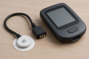
The magnetic pogo pin connector principle combines two separate functions: magnets align and retain the connector halves, while spring-loaded pogo pins create the conductive electrical paths.
As the connector approaches, magnetic attraction helps bring the mating surfaces into position. Mechanical guides control lateral and rotational alignment. The pogo pin plungers then contact the mating pads and compress to a defined working position. That compression creates the normal force required for stable power or signal transfer.
The magnets do not carry the electrical current, set the data rate or automatically eliminate contact resistance. Electrical performance depends on the pogo pin structure, mating pads, compression, PCB or cable transitions, pin layout and control circuitry.
A magnetic pogo pin connector works by using magnetic force to support alignment and retention, mechanical features to control the mating position, and spring-loaded contacts to maintain pressure against conductive pads. A reliable connection requires all three functions to remain within their designed operating ranges.
What Is a Magnetic Pogo Pin Connector?
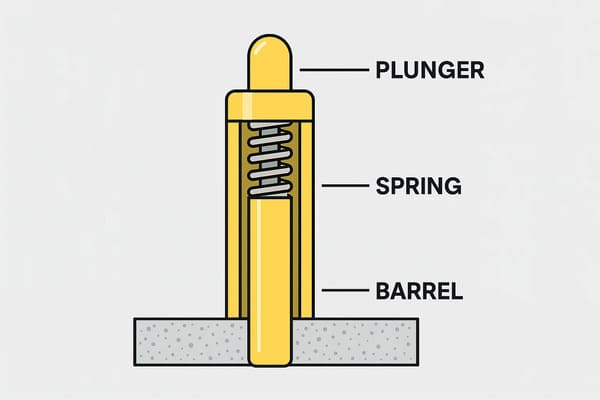
A magnetic pogo pin connector is a contact-based electrical connector containing:
- one or more spring-loaded pogo pins;
- conductive mating pads;
- permanent magnets;
- an insulating housing;
- mechanical guides or locating features;
- PCB, FPC, wire or cable terminations;
- optional detection and protection circuits.
It may transfer:
- DC power;
- charging current;
- low-speed control signals;
- device identification;
- temperature-sensor signals;
- application-specific data.
It is not the same as wireless inductive charging. A magnetic pogo pin connector transfers electricity through direct conductive contact between the pogo pins and mating pads.
Functions of the Main Connector Components
| Component | Primary function | What it does not guarantee |
|---|---|---|
| Permanent magnets | Assist final alignment and provide retention. | Current capacity, contact resistance or signal bandwidth. |
| Pogo pin plunger | Moves axially and contacts the mating pad. | Structural alignment or side-load support. |
| Internal spring | Provides return force and maintains plunger pressure. | A universal force value suitable for every project. |
| Barrel | Guides the plunger and connects to the termination structure. | Stable movement if the plunger is exposed to excessive side load. |
| Mating pad | Provides the external conductive landing surface. | Reliable performance when its size, finish or position is unsuitable. |
| Housing guides | Control lateral position, rotation and final mating distance. | Electrical continuity without correct contact compression. |
The Five Stages of the Magnetic Pogo Pin Connection Cycle
The working principle is easier to understand when the complete mating process is divided into five stages.
- approach and magnetic capture;
- mechanical alignment;
- initial electrical contact;
- working compression and stable conduction;
- controlled separation.
Stage 1: Approach and Magnetic Capture
As the connector halves approach, magnetic attraction begins pulling them together. The effective force depends on the complete magnetic system rather than only the magnet grade.
Relevant factors include:
- magnet dimensions;
- magnet spacing;
- magnet polarity;
- air gap;
- housing-wall thickness;
- adhesive thickness;
- magnetic return components where used;
- mating orientation;
- operating temperature.
The attraction is generally weaker when the connector halves are farther apart and increases as the air gap becomes smaller. This allows the magnets to assist final engagement, but it does not mean they can correct unlimited position error.
What magnetic capture should achieve
- bring the connector into the mechanical capture area;
- encourage the correct mating orientation;
- reduce the manual force required for final engagement;
- provide enough retention to maintain the required pogo pin compression.
What magnetic capture should not be expected to achieve
- correct large lateral or angular errors;
- carry heavy structural loads;
- prevent every incorrect accessory from attaching;
- supports that every pin reaches the correct pad;
- replace electrical power-enable controls.
Stage 2: Mechanical Alignment
After the connector enters the capture area, mechanical features should define its final position.
Common locating features include:
- guide walls;
- recessed mating faces;
- locating posts;
- asymmetrical housings;
- keyed profiles;
- anti-rotation ribs;
- floating mounting plates.
These structures should engage before the pogo pin tips are exposed to substantial lateral movement.
Why magnets alone are not enough
If the connector begins attracting while significantly offset, the magnetic force may pull one surface across the other. This can cause the pogo pin tips to slide across the mating pads before reaching the intended position.
Possible consequences include:
- scratched contact surfaces;
- plunger side loading;
- contact with an adjacent pad;
- uneven initial compression;
- incorrect power-to-signal contact;
- one-sided wear.
Mechanical features should correct large position errors. Magnets should assist final alignment. Pogo pins should provide axial electrical contact.
Stage 3: Initial Electrical Contact
The pogo pin tip first touches the mating pad before reaching its full working compression. At this moment, the connection may be electrically detectable but not yet suitable for the full operating current.
Initial contact may involve:
- only one contact touching first;
- partial contact area;
- low spring force;
- connector tilt;
- temporary contact bounce;
- sliding across the pad.
This stage is important because applying full power too early can create high resistance, inrush current or arcing.
Contact sequencing
Some connector systems use different contact lengths or electronic control to create a sequence such as:
- ground contact engages;
- connector-detection contact engages;
- the device confirms the correct accessory;
- the connector reaches its full mating position;
- the main power path is enabled.
The exact sequence depends on the application. It should be checked during straight, angled and partial mating.
Stage 4: Working Compression and Stable Conduction
After the connector reaches its mechanical stop, the pogo pins should be compressed to their intended working position.
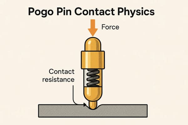
At this position, the spring creates normal force between the plunger tip and mating pad. This force supports electrical stability by creating and maintaining microscopic conductive contact areas.
The apparent contact surfaces may look flat, but at a microscopic level they touch at a limited number of surface high points. These small contact regions are sometimes described as asperity contacts.
Increasing suitable normal force can:
- increase the number or size of conductive contact spots;
- reduce sensitivity to light surface films;
- stabilize the contact during small vibration;
- reduce variation caused by minor surface roughness.
However, more force is not always better. Excessive force can increase wear, pad marking, housing stress and pogo pin load.
The working position must stay inside a defined window
| Condition | Electrical effect | Mechanical effect |
|---|---|---|
| Under-compression | Unstable resistance or intermittent contact. | Low spring force and limited retention margin. |
| Correct working compression | Contact operates inside the validated electrical range. | Plunger remains within the intended force and travel range. |
| Over-compression | May not create a meaningful electrical benefit. | Bottoming, spring stress, PCB loading or housing deformation. |
| Uneven compression | Different resistance across the contact array. | Connector tilt, uneven force and one-sided wear. |
Where Does the Electrical Current Actually Flow?
The exact internal current path depends on the pogo pin design. A simplified connector path may be:
- power source or signal driver;
- cable, FPC or PCB trace;
- connector termination;
- pogo pin barrel and internal conductive interface;
- pogo pin plunger;
- plunger tip;
- mating pad;
- device-side PCB, wire or circuit.
In many pogo pin structures, the intended low-resistance path is primarily through the conductive relationship between the plunger and barrel, while the internal spring mainly provides axial force. Other designs may distribute current differently. The exact internal architecture should be confirmed from the product drawing and test data.
The Four Main Sources of Connector Resistance
The measured connector resistance is normally the combined result of several different sections.
| Resistance source | Influencing factors |
|---|---|
| Bulk conductor resistance | Material conductivity, path length and cross-sectional area. |
| Internal pogo pin resistance | Plunger-to-barrel structure, compression and internal contact design. |
| Tip-to-pad contact resistance | Normal force, surface finish, contamination, wear and contact geometry. |
| Termination resistance | Solder joint, crimp, wire, PCB trace, FPC or cable-head construction. |
Replacing the pogo pin may not solve a high-resistance problem if the actual source is a cable conductor, solder joint, mating pad or device-side PCB trace.
Why Contact Resistance Changes During Use
Contact resistance may vary because of:
- changing pogo pin compression;
- housing movement;
- connector vibration;
- surface contamination;
- plating wear;
- temperature;
- contact oxidation;
- cable or PCB movement;
- uneven current sharing.
A resistance value measured once at room temperature does not describe the complete behavior of the connector.
Useful measurements may include:
- resistance at minimum and nominal compression;
- resistance before and after mating cycles;
- resistance during vibration;
- voltage drop at operating current;
- temperature rise during continuous load;
- variation across multiple contacts and samples.
Why a Magnetic Connector Can Still Experience Signal Loss
Magnetic retention can help maintain engagement, but signal loss may still occur when:
- the pogo pins are under-compressed;
- one side of the connector lifts during cable movement;
- the mating pads are contaminated;
- the plunger is side-loaded or stuck;
- the connector housing flexes;
- the cable or PCB termination is damaged;
- the signal return path is unsuitable;
- offset mating connects the wrong pads;
- the protocol exceeds the validated signal capability.
The presence of magnets does not remove the need for mechanical tolerances, electrical layout and system-level validation.
Magnetic Force Does Not Define Signal Integrity
Signal integrity depends on the complete electrical geometry rather than the holding force alone.
For higher-frequency or higher-speed signals, engineers may need to evaluate:
- signal and return-contact arrangement;
- differential-pair symmetry;
- contact spacing;
- connector-head PCB routing;
- cable construction;
- shield termination;
- impedance discontinuity;
- insertion loss and crosstalk.
A stronger magnet may reduce accidental separation, but it cannot correct an inadequate return path, poor PCB routing or unsuitable pin geometry.
How Pogo Pin Tip Geometry Affects the Contact
The plunger tip determines how the pogo pin contacts the mating pad.
Common tip forms include:
- flat;
- rounded;
- conical;
- crown;
- serrated;
- custom profiles.
| Tip type | Possible benefit | Main consideration |
|---|---|---|
| Flat | Broad contact area on a flat mating pad. | May be sensitive to particles or uneven surfaces. |
| Rounded | Can tolerate moderate angular variation. | Creates a smaller initial contact region. |
| Conical | Creates concentrated contact pressure. | May mark or wear a soft mating pad. |
| Crown or serrated | Can engage irregular or lightly contaminated surfaces. | May increase pad wear and is not a substitute for cleaning. |
The tip and mating pad should be selected as a pair. A tip that works well against a thick metal terminal may be unsuitable for a thin plated PCB pad.
How the Mating Pad Influences Performance
The mating pad affects both electrical contact and mechanical wear.
Relevant parameters include:
- pad diameter or width;
- pad position tolerance;
- surface flatness;
- base material;
- surface finish;
- plating thickness;
- PCB support beneath the pad;
- spacing to adjacent circuits.
A pad should be large enough to accommodate the permitted lateral mating tolerance without allowing the pogo pin to contact an adjacent circuit.
Stage 5: Controlled Separation
During separation, the spring-loaded plungers extend as the magnetic connection opens. Electrical control should remove or reduce power before the main contacts separate when the application involves significant current or hot-plugging risk.
A preferred separation sequence may be:
- the system detects a separation request or loss of full mating;
- operating current is reduced;
- the main power circuit opens electronically;
- the main contacts physically separate;
- detection and ground contacts separate last where required.
The connector should not depend on magnetic separation alone to suppress electrical arcing.
Breakaway behavior depends on direction
The force required to separate the connector can differ under:
- straight axial pull;
- side pull;
- peeling from one edge;
- torsion;
- combined cable bending and pulling.
Controlled breakaway should therefore be specified by direction and tested with the final cable, connector head and device mounting.
Blind Mating Does Not Mean Alignment-Free Mating
A blind-mate connector can be engaged without directly viewing the contact surfaces. It still requires a defined mechanical capture range.
A practical blind-mating design should control:
- maximum lateral offset;
- maximum angular offset;
- rotational orientation;
- mating speed;
- final compression;
- incorrect accessory mating;
- contact sequencing.
Magnets can make blind mating easier, but guides and keyed housings remain important.
Environmental Effects on the Working Principle
The basic operating sequence can be disturbed by environmental conditions.
| Environmental factor | Possible effect on the connector principle |
|---|---|
| Dust | Prevents full contact or increases resistance. |
| Metallic particles | May be attracted by the magnets and bridge adjacent contacts. |
| Moisture | Can create leakage, corrosion or unstable surface films. |
| Oil or adhesive residue | May reduce conductive contact area or restrict plunger movement. |
| Low temperature | Can change cable flexibility, housing dimensions and gasket behavior. |
| High temperature | May affect resistance, spring behavior, magnets, plastics and adhesives. |
A sealed housing may reduce some environmental exposure, but a specific protection rating applies only to the tested complete assembly.
How to Verify the Magnetic Pogo Pin Connector Principle
A useful validation plan should confirm each stage of the mating cycle rather than only checking final continuity.
| Connection stage | Recommended verification |
|---|---|
| Approach | Capture range, magnet polarity and attraction behavior. |
| Alignment | Lateral, angular, rotational and incorrect-accessory mating. |
| Initial contact | Contact order, bounce, partial mating and power-enable timing. |
| Full compression | Working stroke, contact resistance, voltage drop and temperature rise. |
| Dynamic operation | Live continuity during cable movement, vibration and external loading. |
| Separation | Power removal, breakaway direction, arcing and contact condition. |
| Post-aging | Resistance, spring return, retention and surface wear after cycling. |
Common Misunderstandings About the Working Principle
“The magnets conduct the charging current”
Incorrect. The magnets provide mechanical alignment and retention. Current flows through the conductive contacts and their terminations.
“Stronger magnets always produce a better connection”
Incorrect. Excessive magnetic force can increase separation load, housing stress and metallic-debris attraction.
“The strongest magnet grade is always required”
Incorrect. Holding force depends on dimensions, air gap, housing, magnetic circuit and temperature—not grade alone.
“Magnetic alignment eliminates the need for guides”
Incorrect. Guides are often needed to control large positional error, rotation and contact sliding.
“A magnetic connector cannot experience contact wear”
Incorrect. Wear can still result from sliding, vibration, contamination, excessive compression and electrical arcing.
“One contact-force value works for every pogo pin”
Incorrect. Required force depends on contact geometry, electrical load, pad material, pin count, vibration and housing limits.
“Passing a continuity test proves data capability”
Incorrect. High-speed or frequency-sensitive applications require the complete signal path, return path, cable and PCB transition to be evaluated.
“A high cycle count applies to every application”
Incorrect. Cycle-life results apply to the tested connector structure, compression, load, environment and failure criteria.
When the Magnetic Pogo Pin Principle Is Useful
This architecture is commonly considered when:
- the interface mates frequently;
- blind or one-handed mating is useful;
- axial tolerance compensation is required;
- a shallow contact surface is preferred;
- controlled cable breakaway is desirable;
- a removable module must dock repeatedly;
- the connector and mating device can be designed together.
When Another Connector May Be More Suitable
A conventional or standardized connector may be preferable when:
- the connection must remain positively locked under high external load;
- third-party cable compatibility is required;
- the interface must carry a standardized high-speed protocol;
- the environment contains uncontrolled metallic debris;
- exposed contacts cannot be kept electrically safe;
- the connection remains permanent;
- magnetic fields are incompatible with nearby components;
- the system cannot control the mating position.
Information Needed to Apply the Principle to a Real Project
For an engineering review, provide:
- device and application type;
- pin count and pin assignment;
- continuous and peak current;
- operating voltage;
- signal or data requirements;
- available connector dimensions;
- mating direction;
- working compression requirement;
- permitted lateral and angular error;
- retention or breakaway requirement;
- cable or module loading;
- hot-plugging and detection requirements;
- environmental conditions;
- expected mating frequency;
- 2D drawings, 3D models and electrical diagrams.
Frequently Asked Questions
What is the basic magnetic pogo pin connector principle?
Magnets align and retain the connector halves, mechanical features establish the final position, and spring-loaded pogo pins compress against conductive pads to carry power or signals.
Do the magnets carry electrical current?
No. The electrical path passes through the pogo pins, mating pads and associated PCB, cable or wire terminations.
Why do pogo pins need springs?
The spring allows axial movement and maintains contact pressure despite dimensional variation between the connector halves.
Why does compression affect contact resistance?
Suitable normal force helps maintain microscopic conductive contact areas between the plunger tip and mating pad. Too little force can create unstable contact, while excessive force may increase mechanical stress.
Can a magnetic pogo pin connector transmit data?
Yes, for suitable applications. Data performance depends on the protocol, pin arrangement, return path, PCB transition, cable and validation method.
Does magnetic attraction prevent all signal drops?
No. Signal loss can still result from under-compression, contamination, connector tilt, cable faults, poor signal return paths or unsuitable protocol design.
Why are mechanical guides still required?
Guides control lateral, angular and rotational position before the pogo pins reach their working compression. Magnets mainly assist final alignment and retention.
What happens during angled mating?
One side may contact first, creating uneven compression or an unintended electrical sequence. Angled and partial mating should therefore be included in validation.
Is a magnetic pogo pin connector the same as wireless charging?
No. It transfers power through conductive contact. Wireless charging transfers energy through an electromagnetic coupling system without direct electrical contacts.
Can the connector supports one million mating cycles?
No universal cycle-life supports applies to every design. Durability depends on the tested contact structure, compression, electrical load, mating movement, contamination and acceptance criteria.
Conclusion
The magnetic pogo pin connector principle is a combination of magnetic, mechanical and electrical functions.
Magnets bring the connector halves together and provide retention. Mechanical guides control orientation and final position. Pogo pins then compress against the mating pads, creating the normal force required for electrical conduction.
Reliable operation depends on the complete mating cycle. Initial contact must occur safely, every pin must reach its intended working compression, the current path must remain stable during operation and power should be controlled before separation.
Magnets improve usability and can support retention, but they do not automatically supports low resistance, high-speed data, long life or environmental protection. Those characteristics must be designed and validated at the complete connector and device level.
CTP supports custom development of magnetic pogo pin connectors, magnetic cable assemblies, pogo pin connector assemblies and individual pogo pins.
For a new connector project, submit the pin map, current, voltage, working compression, mating direction, signal requirements and device drawings through our Get a Quote & Samples page. The magnetic alignment, contact sequence and conductive path can then be reviewed as one system.
CTP ENGINEERING PATHS
Choose the right path for your project
Move from application requirements to a connector pair, a data-capable cable assembly, or a charging cable configuration. Final specifications are confirmed against an approved drawing and project validation plan.
Magnetic Connectors
Connector geometry, pin layout, mechanical integration and OEM/ODM review.
Engineering overview → 02Magnetic Data Cables
Power and signal allocation, cable exit, interface selection and assembly review.
Cable engineering → 03Magnetic Charging Cables
Browse the complete cable catalog and shortlist a starting structure for customization.
View cable catalog →