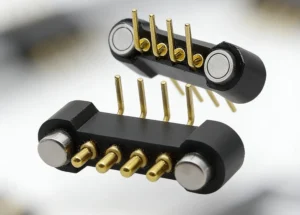
A custom magnetic pogo pin connector should begin with the product
interface requirement rather than with pin count, magnet grade or a
catalog drawing. The engineering team first needs to define which two
assemblies are being connected, how they approach and separate, what
electrical functions cross the interface, how much dimensional variation
exists and what environmental states must be tolerated. Only then should
those requirements be translated into working stroke, Pin Map, magnetic
behavior, connector geometry and production CTQs.
Custom Connector Design Starts with the Interface Contract
A custom magnetic pogo pin connector is not simply a standard pogo pin
array with a different housing.

It forms a mechanical and electrical boundary between two product
assemblies.

Before defining the connector itself, engineers should answer:- Which two assemblies need to connect?
- Why must the interface be removable?
- Who or what performs the mating?
- What functions cross the interface?
- What loads act on the connection?
- What happens before full seating?
- What environmental conditions exist while mated and unmated?
- Which side should be easier to replace or service?
These answers form the beginning of an
interface contract.
A useful design chain is:
    Product Requirement
    →
    Interface Duty
    →
    Mechanical Definition
    →
    Electrical Definition
    →
    Magnetic Definition
    →
    Environmental / Fault States
    →
    Controlled Connector Specification


This is more reliable than beginning with a question such as:

“Can you make us a 6-pin magnetic connector?”

Six contacts may eventually be correct, but the required contact count
should normally be the result of system definition—not the starting point.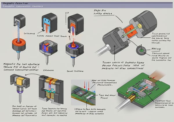
requirement before pin count, magnet layout and housing dimensions are
frozen.
Key 1: Define Every Mating State Before Designing the Contacts
Engineers often design only the final fully seated condition.

A removable magnetic interface can pass through several states before
reaching that position.| Interface State | Engineering Question |
|---|---|
| Separated | Are exposed contacts powered or protected? |
| Approaching | When does magnetic attraction begin to influence motion? |
| Magnetically Captured | Has the connector reached the correct orientation? |
| Partially Mated | Which contacts can engage first? |
| Fully Seated | Are all pogo pins inside their approved working-stroke range? |
| Separating | What electrical state exists while contacts are disengaging? |
Magnetic Attachment Is Not the Same as Valid Electrical Mating
A useful distinction is:


    Magnetic Capture
    ≠
    Mechanical Seating
    ≠
    Valid Electrical Connection


This becomes important when:- power contacts engage before signal contacts;
- only part of a parallel-current array is compressed;
- debris prevents final seating;
- one side of the connector touches first;
- the product can be connected while wet.
The System Can Use the Pin Map to Manage Connection State
Depending on the product, selected contacts may be assigned to:- connection detection;
- module identification;
- pilot or make-first functions;
- controller-managed power enable.
A pilot contact can provide information about the connector state, but the
contact itself does not suppress electrical arcing or supports safe power
sequencing.

The system controller must use that information to perform the required
electrical action.
Define the Intended Mating Sequence
A controlled interface might follow:
    Approach
    →
    Magnetic Capture
    →
    Mechanical Guidance
    →
    Final Seating
    →
    Connection Detection
    →
    Required Validation
    →
    Main Function Enabled


Not every product needs all of these stages.

The important principle is that the connector should be designed around
the actual product workflow rather than only the final CAD position.
Key 2: Build the Mechanical Design Around Datums and Working Stroke
A pogo pin provides controlled compliance along its spring axis.

That compliance is useful because the real product contains dimensional
variation.
A simplified compression relationship is:
S = Hfree - Hseatedwhere:
- S = installed pogo pin compression;
- Hfree = installed free height;
- Hseated = final seated height.
The Connector Drawing Alone Does Not Define Working Stroke
Actual compression can depend on:- pogo pin free-height tolerance;
- PCB thickness;
- solder height;
- housing dimensions;
- mating-target height;
- module flatness;
- assembly variation;
- mechanical-stop position.
Therefore, the design should calculate:


    Minimum Compression
    /
    Nominal Compression
    /
    Maximum Compression


and verify that all three conditions stay inside the approved working
window.
Pogo Pins Should Not Become the Structural Stop
The product should normally use mechanical geometry to define the final
assembled position.

A robust function split is:| Mechanical Function | Preferred Design Element |
|---|---|
| Coarse Approach | User, robot or product geometry |
| X-Y Guidance | Guide walls, bosses or mechanical features |
| Final Position | Mechanical datums and stops |
| Capture / Retention | Magnetic system where useful |
| Electrical Compliance | Pogo pin working stroke |
Magnets Should Not Define Precision Position by Themselves
Magnetic attraction can assist the connector during the final approach,
but it does not automatically create a controlled X-Y-Z datum.
A stronger sequence is:
    Magnetic Capture
    →
    Mechanical Guidance
    →
    Mechanical Datum
    →
    Defined Working Stroke
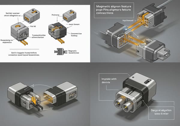
final position and pogo pins provide controlled Z-axis compliance.
Key 3: Build the Pin Map from System Functions, Not from Pin Count
A custom connector creates the opportunity to decide exactly what crosses
the removable product boundary.

The engineering flow should be:


    System Functions
    →
    Electrical Paths
    →
    Pin Map
    →
    Contact Count
    →
    Connector Geometry


A Pin Map may contain:- power;
- power return;
- connection detection;
- module identification;
- control signals;
- selected data signals.
Define the Complete Current Path
Current capability should not be selected from pogo pin diameter alone.A complete conductive path may include:
    Power Source
    →
    PCB / Cable
    →
    Termination
    →
    Pogo Pin
    →
    Contact Interface
    →
    Mating Target
    →
    Device PCB
    →
    Load
A simplified resistance model is:
    Rpath =
    Rsource +
    Rtermination +
    Rpogo +
    Rinterface +
    Rtarget +
    Rload
Voltage drop follows:
Vdrop = I × Rpathand resistive power loss follows:
Ploss = I² × Rpath

Therefore, current validation should consider:- working stroke;
- mating-target condition;
- PCB or cable conductor size;
- termination resistance;
- ambient temperature;
- duty cycle;
- temperature rise.
Parallel Contacts Require Current-Sharing Validation
Multiple pogo pins can be placed in parallel for power or return, but
current may not divide equally.
Sharing can be affected by:
- contact-resistance variation;
- working-stroke variation;
- target flatness;
- module tilt;
- PCB routing;
- termination resistance.
The complete contact array should therefore be validated under
representative mechanical and electrical conditions.
Pin Count Does Not Prove Data Capability
Adding more contacts does not automatically create a high-speed interface.Signal performance may depend on:
- signal-to-return allocation;
- contact pitch;
- contact geometry;
- PCB launch structure;
- reference-plane continuity;
- FPC or cable construction;
- complete channel length;
- crosstalk.
The Pin Map should therefore distinguish between:


    “a contact assigned to data”
and:
“a channel validated for the required signal performance.”
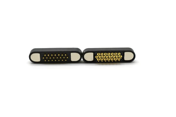
defined system function and the complete electrical architecture is
validated.
Key 4: Design Magnetic Behavior Around Capture, Retention and Breakaway
Magnetic performance should not be reduced to one pull-force number.

A removable connector can experience several different magnetic and
mechanical conditions.| Mechanical Behavior | Engineering Question |
|---|---|
| Capture | How should the interfaces behave during final approach? |
| Seated Retention | What normal-use loads must the connection tolerate? |
| Axial Separation | What happens during straight pull-off? |
| Peel Separation | How does the connector release from one edge? |
| Off-Axis Loading | How do cable force and rotation affect the connection? |
The Magnet Works Against the Complete Reaction System
When pogo pins are compressed, each spring produces a reaction force.

Other reaction forces may come from:- gaskets;
- cable loads;
- module weight;
- dynamic acceleration;
- peel loading.
A simplified design concept is:
    Available Retention
    >
    Pogo Spring Reaction
    +
    Seal Reaction
    +
    Expected Product Loads


The exact margin should follow the actual product requirement.
More Magnetic Force Is Not Automatically Better
Excessive attraction can create:- high separation effort;
- larger closing impact;
- increased housing load;
- more lateral sliding during capture;
- greater attraction of ferromagnetic debris.
Magnetic design should therefore be tuned rather than maximized.Magnet Grade Is Only One Variable
Appropriate magnetic behavior also depends on:- magnet geometry;
- air gap;
- orientation;
- steel return path;
- temperature;
- available package volume;
- product separation direction.
One magnet grade should not be treated as a universal requirement for a
high-quality magnetic connector.
Key 5: Convert the Custom Design into a Production-Controlled Specification
The connector is not finished when the engineering sample works.

The next question is:


    Can the normal production process repeatedly reproduce the approved
    interface?


This requires translating design intent into measurable
Critical-to-Quality characteristics (CTQs).| Design Requirement | Possible CTQ |
|---|---|
| Mechanical Alignment | Pitch, datum position and installed height |
| Pogo Compliance | Working stroke and force at defined compression |
| Electrical Performance | Resistance or voltage drop under defined conditions |
| Magnetic Behavior | Polarity, orientation and defined retention condition |
| Mating Target | Position, flatness, geometry and surface requirement |
| Termination | PCB, FPC, wire or cable requirement |
| Environmental Boundary | Defined seal geometry and production characteristics where required |
Environmental Requirements Should Be Attached to the Complete Assembly
A custom magnetic connector may need to operate around:- water;
- humidity;
- sweat;
- dust;
- salt;
- oil;
- cleaning chemicals;
- metallic debris.
These conditions should not automatically be converted into one generic
“waterproof” specification.

Engineers should define:- the actual exposure;
- mated or unmated state;
- protected sealing boundary;
- post-exposure electrical requirements;
- maintenance or cleaning expectations.
An ingress-protection rating, where required, applies to the defined tested
assembly rather than to the presence of a gasket, potting compound or
magnetic interface alone.
Prototype Validation Should Use the Real Mating Target
The pogo pin side and target side form one electrical contact system.

Qualification should therefore represent:- actual target geometry;
- surface finish;
- flatness;
- working stroke;
- mechanical seating;
- final PCB, FPC or cable termination where practical.
A Golden Sample Should Not Replace the Controlled Drawing
A physical sample can help confirm:- appearance;
- fit;
- mating feel;
- basic function.
But it cannot fully define:- dimensional tolerances;
- working-stroke limits;
- Pin Map;
- contact-force range;
- materials where critical;
- electrical acceptance criteria;
- drawing revision.
The controlled specification should remain the production reference.
mechanical, electrical and magnetic requirements can be measured and
controlled.
The Five Engineering Keys as One Design Workflow
The five keys should not be treated as independent checklist items.

They form one development sequence:


    1. Define Mating States
    ↓
    2. Define Mechanical Datums and Working Stroke
    ↓
    3. Build the Pin Map and Electrical Path
    ↓
    4. Define Magnetic Capture / Retention / Breakaway
    ↓
    5. Convert the Design into CTQs and Production Controls


Changing one layer can force changes in another.
For example:
    More Pogo Pins
    →
    More Spring Reaction
    →
    Different Magnetic Retention Requirement
or:
    Smaller Connector
    →
    Smaller Target Pads
    →
    Tighter Alignment Tolerance
    →
    More Demanding Housing Datum Control
or:
    Higher Current
    →
    Different Pin Map
    →
    Larger Conductive Paths
    →
    More PCB Area
    →
    Different Connector Geometry


This is why custom connector engineering should be performed as a system
problem rather than by optimizing each specification independently.
Avoid Optimizing One Specification at the Expense of the Interface
| Requested Optimization | Possible Trade-Off |
|---|---|
| Smaller Pitch | Less routing space and greater alignment sensitivity |
| More Pins | More spring reaction and larger Pin Map complexity |
| Higher Retention | Higher separation effort and debris attraction |
| Smaller Housing | Less space for magnets, guides, seals and routing |
| Higher Current | More thermal and PCB-path requirements |
| Higher Environmental Protection | Additional sealing, tolerance and validation complexity |
| More Functions per Interface | More complicated connection-state and fault analysis |
What Should Be Frozen Before Tooling?
Before committing to production tooling, the project should ideally have a
controlled definition of:- connector outline;
- mechanical datums;
- mating direction;
- working-stroke window;
- Pin Map;
- mating-target geometry;
- magnet polarity and architecture;
- termination method;
- critical environmental boundaries;
- prototype acceptance criteria;
- production CTQs.
This does not mean every design decision can never change.

It means that the project has an engineering baseline against which future
revisions can be evaluated.
Prototype-to-Production Validation Sequence
A practical custom connector development process is:
    Product Requirement
    →
    Interface Definition
    →
    2D / 3D Concept
    →
    Tolerance Review
    →
    Pin Map Review
    →
    Magnetic / Mechanical Review
    →
    Engineering Sample
    →
    Functional Validation
    →
    Environmental / Lifecycle Validation
    →
    Pilot Production
    →
    CTQ Review
    →
    Production Release
What Should Be Validated on the Engineering Sample?
| Validation Area | Questions to Answer |
|---|---|
| Fit | Does the connector fit the real enclosure and PCB? |
| Mating | Does the product reach the intended mechanical datum? |
| Working Stroke | Are all pogo contacts inside the intended compression range? |
| Pin Map | Are all electrical functions assigned and connected correctly? |
| Power | Are voltage drop and temperature rise acceptable? |
| Signals | Does the required channel perform under representative conditions? |
| Magnetic Behavior | Are capture, retention and separation appropriate? |
| Partial Mating | What occurs before complete seating? |
| Environment | Does the complete defined assembly meet the required exposure condition? |
Information Required to Start a Custom Magnetic Pogo Pin Connector
| Project Input | Information to Provide |
|---|---|
| Product Architecture | Which two assemblies need to connect? |
| Interface Function | Charging, docking, module, service, data or another function |
| Available Space | X, Y and Z connector envelope |
| Mating Method | Manual, blind, automatic or fixture-controlled |
| Mating Tolerance | X-Y-Z and angular variation |
| Pin Map | Power, return, detection, identification and signals |
| Electrical Load | Voltage, continuous current, peak current and duty cycle |
| Signal Requirement | Required control or communication channel |
| Working Stroke | Available minimum, nominal and maximum compression |
| Magnetic Behavior | Capture, retention and separation expectations |
| Environment | Temperature, water, sweat, dust, salt, oil or chemicals |
| Lifecycle | Expected mating and service profile |
| Termination | PCB, FPC, wire or cable |
| Production Forecast | Prototype, pilot and expected annual volume |
| Project Files | 2D drawing, 3D assembly, PCB layout and enclosure reference |
Frequently Asked Questions
What is a custom magnetic pogo pin connector?
It is a spring-contact interface whose contact layout, housing, magnetic
behavior, termination and mechanical geometry are designed around a
specific product rather than selected only from a fixed catalog model.
What can be customized in a magnetic pogo pin connector?
Depending on the project, customization can include connector geometry,
pin count, Pin Map, working stroke, target layout, housing, magnetic
architecture, PCB/FPC/wire termination and environmental structure.
How do I determine the number of pogo pins needed?
Start with the required electrical functions. Define power, return,
detection, identification and signal paths first, then determine the
required contact count and geometry.
How is pogo pin working stroke selected?
Working stroke should be based on the complete product tolerance stack,
including connector height, PCB, solder, housing, mating target and
mechanical-stop variation.
Do stronger magnets make a custom connector better?
Not automatically. Magnetic force should be selected from the required
capture, seated retention, breakaway behavior, spring reaction, package
space and operating environment.
Can a custom magnetic pogo pin connector carry high current?
It can be designed as part of a higher-current interface, but actual
capability depends on the complete conductive path, working stroke,
mating target, termination, PCB or cable design, duty cycle and
temperature-rise validation.
Can custom magnetic pogo pins carry data signals?
Selected signal functions can be incorporated into the Pin Map, but data
capability depends on contact geometry, signal-return allocation, PCB
transitions, cable or FPC construction and the complete channel.
Can a custom magnetic connector be waterproof?
It can be integrated into an ingress-protected assembly, but the actual
rating depends on the complete feedthrough, housing, seal, termination and
enclosure configuration and must be validated on the defined assembly.
Why is partial mating important in custom magnetic connectors?
Magnetic attraction may begin before final seating. Engineers should
evaluate which contacts can engage during approach and whether power,
detection or signal functions require controlled sequencing.
Should the magnet determine final connector position?
Normally no. Magnets can assist capture and retention, while mechanical
datums and stops should establish final position and pogo pin compression.
What should be completed before custom tooling starts?
The project should have an agreed connector envelope, mechanical datums,
Pin Map, working-stroke window, mating target, magnetic architecture,
termination method and major CTQs before production tooling is released.
What is the difference between a prototype and a production-ready custom connector?
A prototype shows that a design can work. A production-ready connector
requires controlled drawings, measurable CTQs, validated processes and
evidence that normal production can repeatedly reproduce the approved
design.
Request a Custom Magnetic Pogo Pin Engineering Review
Explore

    CTP custom magnetic connector solutions

for removable charging, docking and modular hardware interfaces.

Review

    pogo pin and spring-contact connector solutions

for different contact layouts and mounting structures.

Learn more about CTP engineering and manufacturing capabilities on the

    About Us page
. Submit your product envelope, Pin Map, working stroke, voltage, current,
mating tolerance, magnetic behavior, environmental requirements and
available 2D or 3D files to CTP for an engineering review.
The project can be reviewed from the interface level first so that
mechanical datums, electrical functions, magnetic behavior and
production CTQs are defined before tooling is frozen.
Final electrical performance, signal capability, magnetic behavior,
environmental protection, lifecycle and production capability should
be confirmed against the approved connector revision and
project-specific validation conditions.
CTP ENGINEERING PATHS
Choose the right path for your project
Move from application requirements to a connector pair, a data-capable cable assembly, or a charging cable configuration. Final specifications are confirmed against an approved drawing and project validation plan.
Magnetic Connectors
Connector geometry, pin layout, mechanical integration and OEM/ODM review.
Engineering overview → 02Magnetic Data Cables
Power and signal allocation, cable exit, interface selection and assembly review.
Cable engineering → 03Magnetic Charging Cables
Browse the complete cable catalog and shortlist a starting structure for customization.
View cable catalog →