
Magnetic pogo pin connectors can support efficient production and test
interfaces when they are used to solve a defined manufacturing problem.
The main value is not simply faster magnetic attachment. A well-designed
fixture separates DUT positioning, final capture, pogo pin compression,
seating confirmation, electrical test and maintenance into controlled
functions. Production efficiency then comes from fewer retries, predictable
contact engagement, faster wear-part replacement and better control of the
fixture over its service life.
Production Efficiency Starts with the Interface Process, Not the Connector
When an electronics production line suffers from slow testing, repeated
fixture adjustments or unstable contact, the first reaction is often to
replace the connector.

But the connector is only one part of the manufacturing interface.
A typical station may include:
- the device under test (DUT);
- a mechanical nest or fixture;
- guidance features;
- magnetic capture;
- pogo contacts;
- target pads;
- test electronics;
- connection detection;
- software test sequence;
- maintenance and cleaning procedures.
Therefore, the correct manufacturing question is not:


    “Will a magnetic connector make the line faster?”
It is:
    “Which part of the current production cycle is creating delay,
    retries, wear or maintenance?”
A useful process chain is:
    DUT Arrives
    →
    Gross Positioning
    →
    Final Guidance
    →
    Magnetic Capture
    →
    Mechanical Seating
    →
    Pogo Compression
    →
    Connection Confirmation
    →
    Test / Power
    →
    Release


Magnetic pogo pins create the most value when they improve one or more
specific steps in this sequence.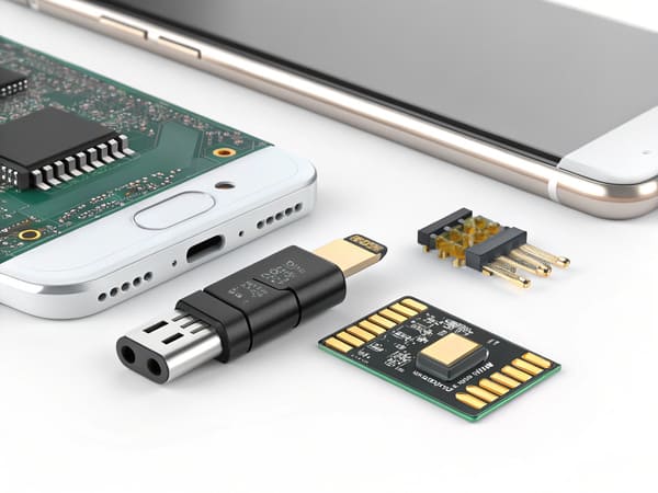
contact engagement and maintenance workflow—not the connector alone.
Lever 1: Let the Fixture Handle Gross Positioning and the Pogo Interface Handle Final Compliance
One of the most important production-fixture design principles is to avoid
asking the pogo pin array to correct large positioning errors.

The fixture should normally handle:- gross X-Y positioning;
- rotation control;
- DUT support;
- large approach errors;
- structural loads.
The magnetic system can then assist final capture where useful.

The pogo pins provide controlled electrical compliance along their spring
axis.
A stronger function split is:
| Production Function | Preferred Control Element |
|---|---|
| Gross DUT Position | Fixture nest, robot or mechanical locator |
| Final X-Y Guidance | Datum, guide wall, pin or chamfer |
| Final Capture | Magnetic assistance where useful |
| Final Z Position | Mechanical stop |
| Electrical Compliance | Pogo pin working stroke |
Magnetic Capture Does Not Replace Fixture Accuracy
A magnetic field can help pull the DUT or mating module toward the intended
interface.

It should not be expected to establish a precision datum by itself.

If the fixture enters the magnetic capture region with excessive:- X-Y offset;
- angular error;
- height error;
- tilt;
the interface can still experience:- uneven pogo compression;
- partial contact;
- target-pad edge landing;
- side loading;
- repeated test retries.
Working Stroke Should Absorb Controlled Z Variation Only
A simplified relationship is:
S = Hfree - Hseatedwhere:
- S = actual pogo pin compression;
- Hfree = installed free height;
- Hseated = final seated height.
Production variation may come from:- fixture stack-up;
- DUT housing tolerance;
- PCB position;
- target height;
- pogo installed height;
- wear in the fixture.
Minimum, nominal and maximum conditions should remain inside the approved
working-stroke window.
Lever 2: Confirm Seating Before Starting the Test Sequence
A large amount of production time can be lost when the test system begins
before the DUT has reached a valid contact state.

This can create:- failed tests that pass on retry;
- unnecessary operator intervention;
- repeated docking cycles;
- good units sent to rework;
- longer test takt time.
A magnetic interface makes this especially important because:


    Magnetic Capture
    ≠
    Mechanical Seating
    ≠
    Valid Electrical Contact
Use a Defined Connection-State Sequence
A production station can be designed around:
    DUT Present
    →
    Fixture Engaged
    →
    Magnetic Capture
    →
    Mechanical Seat Confirmed
    →
    Required Contacts Valid
    →
    Test Start


The exact method depends on the station.
Possible confirmation methods may include:
- fixture position sensing;
- mechanical limit detection;
- dedicated detection contacts;
- electrical continuity check;
- fixture-controller logic.
Do Not Use the Main Functional Test as the First Proof of Contact
If the DUT only discovers poor seating after a long functional test begins,
every bad docking event consumes unnecessary station time.

A short pre-check can sometimes distinguish:


    Contact Problem
    ↓
    from
    ↓
    Product Functional Failure


This helps reduce the risk of treating a fixture problem as a product
defect.
Partial Mating Should Be Treated as a State
If only some contacts are engaged, the interface may still show limited
continuity while being unsuitable for the full test.

This is especially important when the contact array includes:- parallel power contacts;
- multiple grounds;
- communication lines;
- identification or control contacts.
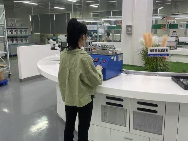
mechanical and electrical state rather than immediately after magnetic
attachment.
Lever 3: Design the Fixture Head as a Replaceable Wear Module
Every high-cycle production contact system contains wear components.

The goal is not to pretend the interface is wear-free.

The better manufacturing strategy is to decide:


    Which part should wear, and how quickly can that part be replaced?
Possible Wear Components Include
- pogo pins;
- target pads;
- fixture guides;
- contact modules;
- cable assemblies;
- mechanical stops.
If these are buried inside a large fixture, maintenance can require:- fixture disassembly;
- re-alignment;
- rewiring;
- extended station downtime.
A Modular Fixture Head Can Reduce Maintenance Time
A production interface can instead be divided into:


    Main Fixture
    ↓
    Replaceable Contact Module
    ↓
    Pogo Array + Target / Cable Interface


The replaceable module can be designed with controlled:- mechanical datums;
- connector position;
- Pin Map;
- cable or PCB termination;
- working height.
This can reduce the amount of fixture requalification required after normal
maintenance.
Design for MTTR, Not Only Contact Life
Long contact life is useful, but maintenance economics also depend on
Mean Time to Repair (MTTR).

A fixture contact lasting longer but requiring a long, difficult replacement
may be less production-friendly than a modular interface that can be changed
quickly and predictably.

Useful maintenance questions include:- Can the contact module be replaced without disturbing the fixture datum?
- Is a spare module available?
- Does replacement require soldering?
- Does the station require recalibration afterward?
- Can the operator identify the correct revision quickly?
Lever 4: Monitor Contact Degradation Before It Becomes a Line Failure
A pogo fixture does not normally transition instantly from “good” to
“failed.”

Degradation can develop through:- contact-surface wear;
- contamination;
- spring-force drift;
- working-height change;
- target wear;
- fixture looseness;
- cable or termination degradation.
If the fixture is only maintained after a station stops working, the
production line may experience a long period of:- higher retry rate;
- intermittent false failures;
- operator cleaning;
- repeated fixture adjustment.
Use Process Indicators Instead of a Universal Cycle Number
A statement such as “replace the contacts every a model-specific cycle-life target validated under defined test conditions” may be
simple, but it ignores the real operating condition.

Useful maintenance indicators may include:- test retry rate;
- contact resistance trend;
- voltage-drop trend;
- fixture seating retries;
- visual contamination;
- measured working height;
- defined cycle count combined with inspection.
Trend Data Can Be More Useful Than One Pass/Fail Limit
For example:
    Stable Fixture
    →
    Low Retry Rate
    →
    Contact Parameter Stable
then:
    Progressive Wear / Contamination
    →
    Retry Rate Increases
    →
    Contact Parameter Drifts
    →
    Planned Maintenance


This allows the fixture to be serviced before it begins to create large
amounts of production disruption.
Cleaning Should Be Defined, Not Improvised
Production operators frequently respond to unstable contacts by manually
wiping or cleaning the fixture.

The cleaning process should define:- approved cleaning method;
- approved fluid where applicable;
- cleaning frequency;
- inspection criteria;
- when cleaning is no longer sufficient and the module must be replaced.
Self-wiping contact motion should not be interpreted as a self-cleaning
system.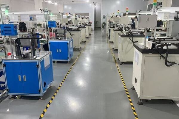
before contact degradation creates repeated line interruptions.
Lever 5: Measure Efficiency at the Station Level, Not from the Connector Specification
A magnetic pogo pin can support a faster fixture architecture, but the
connector itself does not create a guaranteed cycle-time improvement.

Production efficiency should be evaluated at station level.
Relevant metrics may include:
| Production Metric | What It Can Reveal |
|---|---|
| Docking Time | Whether the interface reduces mating effort |
| Test Retry Rate | Whether contact engagement is repeatable |
| Fixture-Induced False Failures | Whether the station is creating measurement errors |
| Cleaning Frequency | How quickly contamination affects the interface |
| Fixture Maintenance Time | How serviceable the contact module is |
| Contact Module Replacement Interval | Actual wear behavior under the real process |
| Station Availability | Overall effect of contact and fixture downtime |
Compare Before and After Using the Same Process Boundary
If a magnetic interface replaces another fixture, compare:


    Existing Station
    vs
    Proposed Station
using the same:
- DUT;
- test scope;
- operator assumptions;
- production volume;
- maintenance window;
- pass/fail criteria.
This avoids assigning every production improvement to the connector when
other fixture or software changes were made at the same time.
Efficiency Improvement Must Be Measured
Claims such as:- 60% faster cycle time;
- 99.9% first-pass yield;
- near-zero fixture downtime;
should only be used when they come from a defined production study under
representative conditions.

Without that evidence, the correct statement is that the architecture
may reduce mating, retry or maintenance burden when those
issues exist in the current process.
Magnetic Pogo Pin Fixtures Do Not Eliminate the Need for Mechanical Design
A common mistake is to assume that magnetic self-capture allows the fixture
to eliminate precision mechanical features.

In reality:


    Magnet
    =
    Capture / Retention


    Mechanical Fixture
    =
    Datum / Guidance / Structural Load


    Pogo Pin
    =
    Electrical Contact / Z Compliance


These are three different jobs.

A robust production interface lets each part perform the job it is best
suited to control.
What About Electrical Test Accuracy?
Production efficiency also depends on avoiding fixture-induced measurement
variation.

The contact system should therefore match the measurement being performed.
For power tests
Consider the complete conductive path:


    Instrument
    →
    Fixture Cable
    →
    Termination
    →
    Pogo Contact
    →
    DUT Target
    →
    DUT Circuit


Voltage drop and heating should be evaluated when meaningful current passes
through the fixture.
For low-resistance measurements
If fixture-contact resistance is significant relative to the parameter being
measured, the measurement architecture may need to separate force and sense
paths or use another appropriate measurement method.

The required method depends on the measurement target.
For digital signals
Pin count alone does not establish signal capability.Channel performance can depend on:
- contact arrangement;
- ground placement;
- fixture PCB;
- cable structure;
- signal return path;
- complete channel length.
The production fixture should be validated for the actual electrical test
requirement.
Where Magnetic Capture Is Useful—and Where It May Add Little Value
| Production Situation | Magnetic Capture Value |
|---|---|
| Frequently Docked DUT | Can reduce final approach burden |
| Existing Magnetic Product Interface | Can reuse the product’s intended mating architecture |
| Robot or Automatic Station | Can assist final capture after gross positioning |
| Fixture Already Positively Clamped | May provide little additional retention value |
| High Metallic-Debris Environment | Requires careful contamination assessment |
| Permanent Internal Test Connection | Magnetic architecture may be unnecessary |
Production Fixture CTQs to Define Before Release
A fixture that works once is not automatically production-ready.Critical-to-quality characteristics may include:
| CTQ Area | Possible Control |
|---|---|
| Contact Position | Pitch, datum location and installed height |
| Working Stroke | Minimum, nominal and maximum compression |
| Mechanical Seating | Defined fixture stop and DUT position |
| Magnetic System | Polarity, location and required capture / retention behavior |
| Electrical Path | Defined continuity, resistance or voltage-drop criterion |
| Replaceable Module | Repeatable datum after replacement |
| Revision Control | Fixture head, Pin Map and DUT revision compatibility |
A Better Production-Interface Development Flow
A practical workflow is:


    Identify Production Bottleneck
    →
    Define DUT Positioning
    →
    Define Fixture Datum
    →
    Define Working Stroke
    →
    Define Connection-State Check
    →
    Define Electrical Test Path
    →
    Build Replaceable Fixture Module
    →
    Pilot Run
    →
    Measure Retry / Maintenance Data
    →
    Set Maintenance Limits
    →
    Production Release
Information Needed for a Production Fixture Review
| Project Input | Information to Provide |
|---|---|
| Production Step | Functional test, charging, programming, calibration or another process |
| DUT Geometry | 2D / 3D location of the contact interface |
| Cycle Requirement | Expected daily and program-level contact frequency |
| Fixture Method | Manual, pneumatic, robotic or another approach |
| Mating Tolerance | X-Y-Z and angular variation |
| Working Stroke | Minimum, nominal and maximum compression |
| Pin Map | Power, ground, sense, communication and control functions |
| Electrical Load | Voltage, current and test-signal requirements |
| Connection Detection | How valid seating will be confirmed |
| Environment | Dust, metallic debris, oil, cleaning or other exposure |
| Maintenance Target | Required replacement time and cleaning strategy |
| Current Problem | Retry rate, wear, downtime, alignment or other bottleneck |
Frequently Asked Questions
Can magnetic pogo pin connectors improve production efficiency?
They can when magnetic capture, repeatable contact engagement or modular
fixture design removes a real production bottleneck. The improvement should
be measured at station level rather than assumed from the connector type.
Do magnetic pogo pins eliminate the need for a precision fixture?
No. The fixture should normally control gross positioning, mechanical
datums and structural loads. Magnets can assist final capture, while pogo
pins provide controlled electrical compliance.
Can magnetic pogo pins reduce test retries?
They may help when retries are caused by mating inconsistency, but valid
seating should still be detected before the main test begins. The root cause
of existing retries should be confirmed first.
Should the test start as soon as the magnets attach?
Not necessarily. Magnetic attachment does not prove that the DUT has reached
its final mechanical position or that all required contacts are valid.
How long do pogo pins last in a production fixture?
There is no universal cycle value. Life depends on working stroke, contact
force, target material, contamination, electrical loading, alignment,
cleaning and the actual fixture duty cycle.
How should pogo pin fixture maintenance be scheduled?
Maintenance can combine cycle counts with process indicators such as retry
rate, contact-resistance trend, seating retries, visual contamination and
working-height inspection.
Why use a replaceable pogo pin fixture module?
It can isolate normal contact wear in a smaller serviceable assembly,
reducing fixture disassembly and potentially shortening maintenance time.
Does tape-and-reel packaging mean a pogo connector is SMT-ready?
No. Production compatibility also depends on pick-up geometry, PCB pads,
coplanarity, reflow conditions, solder process and post-reflow installed
height.
Are magnetic pogo pins better than normal pogo pins for production fixtures?
Not universally. Magnetic capture is useful when removable docking or final
approach assistance creates value. A conventional pogo fixture may be
simpler when the DUT is already mechanically clamped.
Can pogo pins be used for high-current production testing?
They can be designed for power testing, but the complete fixture path,
contact compression, termination, temperature rise and duty cycle should be
validated.
Can pogo fixtures support high-speed data testing?
Potentially, but pin count alone does not prove signal capability. The
complete fixture channel, return path, PCB, cable and contact geometry must
meet the required electrical performance.
What should I provide for a custom production pogo fixture interface?
Provide the DUT geometry, production step, Pin Map, electrical load,
required working stroke, mating tolerance, cycle frequency, fixture method,
current production bottleneck and available 2D or 3D files.
Request a Production Interface Engineering Review
Explore

    CTP custom magnetic connector solutions

for removable production, charging and docking interfaces.

Review

    pogo pin and spring-contact connector solutions

for production test, board and fixture contact structures.

Learn more about CTP engineering and manufacturing capabilities on the

    About Us page
. Submit your DUT interface, Pin Map, working stroke, mating tolerance,
electrical load, cycle requirement, fixture structure and current
production bottleneck to CTP for an engineering review.
The interface can be reviewed around fixture positioning, contact
engagement, seating confirmation, replaceable wear parts and maintenance
strategy before the production fixture is frozen.
Final lifecycle, electrical performance, dynamic behavior and
maintenance interval should be confirmed against the approved fixture
revision and representative production conditions.
CTP ENGINEERING PATHS
Choose the right path for your project
Move from application requirements to a connector pair, a data-capable cable assembly, or a charging cable configuration. Final specifications are confirmed against an approved drawing and project validation plan.
Magnetic Connectors
Connector geometry, pin layout, mechanical integration and OEM/ODM review.
Engineering overview → 02Magnetic Data Cables
Power and signal allocation, cable exit, interface selection and assembly review.
Cable engineering → 03Magnetic Charging Cables
Browse the complete cable catalog and shortlist a starting structure for customization.
View cable catalog →
