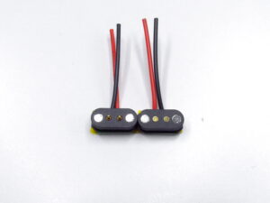
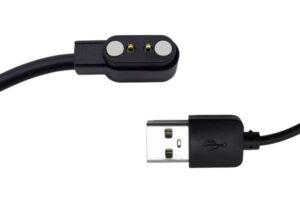
A custom magnetic pogo pin project rarely fails because the customer cannot find a connector with the correct number of pins. Projects are more likely to stall because electrical requirements, available space, magnetic force, working stroke, cable structure and production tolerances were not defined together at the beginning.
A capable custom magnetic pogo pin supplier should therefore do more than quote a similar product. The supplier should translate the customer’s device requirements into a controlled connector architecture, identify the main technical risks, build prototypes for specific learning objectives and prepare the design for repeatable manufacturing.
A prototype that can charge a device is not automatically ready for mass production. Production release also requires controlled dimensions, approved materials, defined inspection methods, stable assembly processes and documented acceptance criteria.
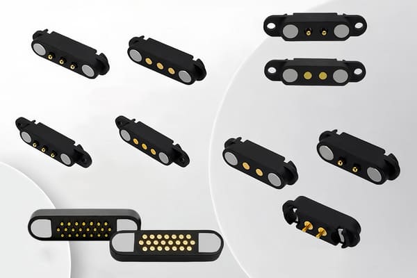
What a Custom Magnetic Pogo Pin Supplier Actually Develops
The final connector may include much more than pogo pins and magnets. Depending on the project, the supplier may need to coordinate:
- individual spring-loaded contacts;
- mating pads or fixed contacts;
- permanent magnets and magnetic steel parts;
- plastic or metal housings;
- PCB, FPC, wire or cable terminations;
- overmolding, insert molding or potting;
- mechanical guides and anti-mismating features;
- sealing structures;
- assembly fixtures and test fixtures;
- packaging and orientation control.
The design process must therefore connect the device architecture with the connector structure. Selecting each component separately can create conflicts later in the project.
Stage 1: Convert the Application into Engineering Inputs
The first stage is not drawing the connector. It is defining what the interface must do inside the finished device.
The customer and supplier should clarify four groups of design inputs.
Electrical inputs
- number of power, ground and signal circuits;
- continuous and peak current;
- operating voltage;
- acceptable voltage drop;
- signal type and data rate;
- hot-plugging requirement;
- grounding and contact-sequencing requirements;
- short-circuit or reverse-polarity risks.
Mechanical inputs
- maximum connector length, width and height;
- mating direction;
- available PCB and enclosure space;
- allowable radial and angular misalignment;
- required magnetic retention or breakaway force;
- expected cable pull and side load;
- mating-cycle target;
- mounting and assembly method.
Environmental inputs
- working and storage temperature;
- humidity and condensation;
- sweat, dust, oil or chemical exposure;
- vibration and shock conditions;
- metallic debris risk;
- waterproofing or enclosure-sealing requirement;
- cleaning and maintenance methods.
Production inputs
- prototype quantity;
- annual forecast;
- target production start date;
- acceptable tooling investment;
- customer assembly process;
- inspection and documentation requirements;
- packaging and shipment method.
| Customer input | Why the supplier needs it |
|---|---|
| Continuous current | Used to evaluate pogo pin size, parallel contacts, wire gauge, voltage drop and temperature rise. |
| Available connector height | Limits pogo pin length, working stroke, housing thickness and magnet dimensions. |
| Breakaway requirement | Determines the balance between magnetic retention, spring load and cable-pull behavior. |
| Environmental exposure | Influences plating, housing, sealing, spacing and contamination-control decisions. |
| Annual volume | Affects tooling, automation, assembly method, test fixtures and cost structure. |
Stage 2: Perform a Feasibility and Risk Review
After receiving the initial inputs, the custom magnetic pogo pin supplier should determine whether the requirements are compatible with each other.
Typical conflicts include:
- high current in a very small connector area;
- strong retention combined with easy one-handed separation;
- small pin pitch combined with high voltage;
- large working stroke in a low-profile enclosure;
- high-speed data in an uncontrolled contact layout;
- waterproofing combined with low magnetic force;
- high mating-cycle expectations with abrasive contamination;
- tight tolerances combined with a low-cost molding process.
The supplier should identify these conflicts before finalizing the structure rather than attempting to solve them after tooling has started.
Recommended feasibility outputs
The customer should receive a preliminary review covering:
- recommended connector architecture;
- estimated connector dimensions;
- proposed pin count and contact allocation;
- recommended mounting method;
- estimated magnetic-force range;
- main electrical and mechanical risks;
- items requiring testing;
- existing components that may be reused;
- new tooling that may be required;
- expected prototype route.
The project should not move into detailed design until the customer and supplier agree on the connector architecture, major trade-offs and unresolved technical risks.
Stage 3: Create the Interface Control Design
The next stage is converting the concept into a controlled mechanical and electrical interface.
The design should define how the connector interacts with the customer’s enclosure, PCB and cable assembly. It should not be limited to the supplier’s internal component dimensions.
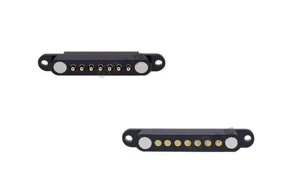
Mechanical definition
The mechanical drawing should normally include:
- overall dimensions;
- mounting dimensions;
- pin pitch;
- pogo pin installed height;
- free height and working height;
- housing alignment features;
- magnet position and polarity;
- mating-pad dimensions;
- critical clearances;
- cable or PCB exit direction;
- customer-side installation reference.
Electrical definition
The electrical specification should define:
- pin numbering;
- power, ground and signal allocation;
- connector orientation;
- current and voltage requirements;
- continuity requirements;
- contact-resistance acceptance criteria;
- insulation requirements where applicable;
- wire and cable assignments;
- shield or ground termination;
- detection or sequencing contacts.
Material definition
The supplier should also document:
- pogo pin component materials;
- contact plating system;
- magnet specification;
- plastic or metal housing materials;
- wire and cable materials;
- adhesive, potting or overmolding materials;
- surface-finish requirements.
Stage 4: Build Prototypes for Specific Learning Objectives
Prototype development should not be treated as a single step where several samples are produced and sent to the customer without a defined evaluation plan.
Different prototype rounds may answer different questions.
Appearance or fit prototype
This prototype may use simplified materials or manufacturing methods to verify:
- overall size;
- enclosure fit;
- mating direction;
- cable exit;
- user handling;
- visual appearance.
Functional prototype
A functional sample should evaluate:
- electrical continuity;
- pogo pin compression;
- magnetic alignment;
- retention and breakaway behavior;
- device charging or operation;
- basic assembly compatibility.
Engineering prototype
An engineering prototype should be closer to the planned production materials and structure. It may be used for:
- contact-resistance testing;
- voltage-drop testing;
- temperature-rise testing;
- mating-cycle testing;
- cable bending and pull testing;
- environmental evaluation;
- customer assembly trials.
Each prototype shipment should identify:
- sample revision;
- drawing revision;
- materials used;
- known differences from production intent;
- tests already completed;
- questions the customer should evaluate.
Stage 5: Verify the Complete Connector System
Testing individual pogo pins is useful, but the final decision should be based on the assembled connector, cable and device interface.
The validation plan should be connected to the customer’s actual use conditions.
| Validation area | What should be evaluated |
|---|---|
| Dimensional | Installed height, pitch, housing size, magnet position, mating alignment and stroke. |
| Electrical | Continuity, contact resistance, voltage drop, insulation and temperature rise. |
| Mechanical | Spring force, magnetic retention, breakaway, cable pull, side load and mating durability. |
| Dynamic | Movement, vibration, shock and electrical interruption during use. |
| Environmental | Temperature, humidity, contamination, corrosion exposure and sealing performance. |
| User interaction | One-handed docking, incorrect approach, accidental pull and repeated daily use. |
Define acceptance criteria before testing
Testing without defined acceptance criteria can create disagreement after the samples have already been produced.
The project should define, where applicable:
- maximum contact resistance;
- maximum voltage drop;
- maximum temperature rise;
- acceptable retention-force range;
- acceptable separation-force range;
- required mating-cycle count;
- maximum allowable interruption;
- appearance acceptance criteria;
- allowable dimensional variation;
- post-test functional requirements.
Stage 6: Freeze the Production Design
After the engineering samples pass the agreed evaluation, the design must be formally frozen before production tooling and process preparation are completed.
The design-freeze package should include:
- approved 2D drawing;
- approved 3D model where required;
- approved pin map;
- approved bill of materials;
- material and plating specifications;
- approved cable specification;
- critical-to-quality characteristics;
- inspection methods;
- approved prototype or reference sample;
- packaging specification;
- revision history.
The customer and supplier should also agree on which changes require customer approval.
Typical controlled changes include:
- pogo pin structure;
- spring force;
- plating thickness or composition;
- magnet grade or supplier;
- plastic material;
- wire gauge or cable supplier;
- tooling;
- production site;
- assembly process;
- inspection method.
Stage 7: Prepare the Process for Pilot Production
Moving from prototype to production requires more than increasing the order quantity. Prototype assembly may use manual adjustments that are not suitable for stable batch production.
The supplier should prepare:
- production process flow;
- assembly work instructions;
- tooling and fixtures;
- magnet-polarity control;
- pogo pin height-control method;
- cable soldering or crimping controls;
- adhesive or overmolding parameters;
- electrical test fixtures;
- inspection standards;
- lot-traceability method;
- packaging method.
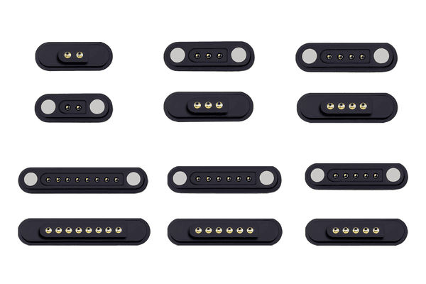
Why a pilot build matters
A pilot build allows the supplier and customer to evaluate the production process before full-volume release.
The pilot should verify:
- whether production drawings are complete;
- whether operators understand the process;
- whether tooling and fixtures work as intended;
- whether critical dimensions remain stable;
- whether the inspection plan detects actual risks;
- whether customer assembly remains consistent;
- whether packaging protects the connector;
- whether production cycle time matches the plan.
Problems found during pilot production should be resolved through controlled corrections rather than informal manual sorting.
Stage 8: Release Mass Production with Traceable Controls
Mass production should only begin after the product definition, process, inspection method and acceptance criteria have been approved.
Routine production control may include:
- incoming-material verification;
- critical-dimension inspection;
- spring-force or installed-height checks;
- magnet-polarity confirmation;
- continuity and pin-map testing;
- contact-resistance sampling;
- retention-force sampling;
- cable length and appearance inspection;
- lot labeling;
- shipment records.
The inspection frequency should reflect the risk and process capability. Not every characteristic requires the same inspection method or sample quantity.
Production records should answer three questions
- Which materials and process conditions were used for this lot?
- What inspection results were recorded before shipment?
- Which customer shipment received the lot?
Common Reasons Custom Magnetic Pogo Pin Projects Stall
Development delays are often caused by unresolved decisions rather than component availability.
| Project problem | Typical consequence |
|---|---|
| Current requirement is not confirmed | Pin size, cable gauge and connector dimensions cannot be finalized. |
| Only an appearance image is provided | The supplier cannot evaluate enclosure fit, tolerance or assembly method accurately. |
| Magnetic force is described only as “strong” | The connector may detach too easily or become difficult to separate. |
| Prototype changes are not recorded | The approved sample and production drawing may represent different designs. |
| Testing begins before criteria are agreed | Customer and supplier may interpret the same test result differently. |
| The connector is tested outside the final device | Housing tolerance, PCB routing, cable load and actual thermal conditions may be missed. |
| Mass production starts directly after one sample | Assembly variation and process bottlenecks may only appear after volume increases. |
What to Send for a Faster and More Accurate Quotation
A custom magnetic pogo pin supplier can provide a more useful quotation when the project information is complete.
Recommended inputs include:
- application and device type;
- pin count and pin assignment;
- continuous and peak current;
- voltage and signal requirements;
- available connector length, width and height;
- mating direction;
- required retention or breakaway behavior;
- PCB, FPC, wire or cable termination;
- working environment;
- mating-cycle target;
- prototype quantity;
- expected annual volume;
- target project schedule;
- 2D drawings, 3D models or device samples.
When some parameters are still unknown, clearly mark them as open decisions. The supplier can then recommend a range rather than assuming a fixed value.
Questions to Ask Before Approving the Project Plan
- Which requirements have already been confirmed?
- Which requirements are still assumptions?
- Which components are existing and which require customization?
- What are the three highest technical risks?
- What will each prototype round verify?
- Which tests will be completed by the supplier?
- Which tests must be completed in the customer’s final device?
- What changes are allowed after sample approval?
- What must be completed before pilot production?
- What evidence is required before mass-production release?
Frequently Asked Questions
How long does a custom magnetic pogo pin project take?
The schedule depends on whether existing pogo pins, magnets and housings can be reused, whether new tooling is required and how many prototype and validation rounds are needed. A complete project schedule should separate design review, prototype preparation, testing, tooling, pilot production and mass-production release.
Can an existing magnetic connector be modified instead of creating a new design?
Often yes. Existing contact layouts, housings or cable structures may reduce tooling and development effort. However, the existing design still needs to be checked against the new current, space, retention, pin-map and environmental requirements.
When should tooling begin?
Production tooling should normally begin after the main interface dimensions, pin map, materials and unresolved risks have been reviewed. Starting tooling too early can create expensive changes later.
Is a working sample enough for mass-production approval?
No. The sample should also be connected to an approved drawing, material specification, inspection standard and production process. Pilot production is useful for confirming that the design can be manufactured consistently.
Who should define the validation plan?
The customer should define the final application requirements, while the supplier can recommend connector-level tests and acceptance methods. The final plan should clearly assign responsibilities between both parties.
Can a magnetic pogo pin supplier supports controlled quality requirements?
No responsible supplier should promise that every future unit will be free from all possible defects. The practical objective is to define critical requirements, control the manufacturing process, detect nonconforming products and improve the process when problems occur.
What is the difference between a prototype and a pilot build?
A prototype is primarily used to evaluate the design. A pilot build uses the intended production process, tooling, work instructions and inspection methods to evaluate manufacturing readiness.
Conclusion
Choosing a custom magnetic pogo pin supplier is not only a purchasing decision. It is the beginning of a joint engineering and manufacturing process.
A well-managed project moves through clear stages: application definition, feasibility review, controlled design, learning prototypes, validation, design freeze, pilot production and mass-production release. Each stage should produce specific evidence and resolve specific risks before the next investment is made.
CTP supports the development of custom magnetic pogo pin connectors, magnetic cable assemblies, pogo pin connector assemblies and individual pogo pins.
For a new project, submit your pin map, current requirements, available connector space, mating direction, environmental conditions and drawings through our Get a Quote & Samples page. The project can then begin with a structured feasibility and connector-architecture review.