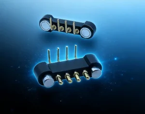
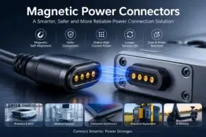
A custom magnetic USB cable can reduce repeated mechanical stress on a device charging interface by moving the daily mating action away from a conventional plug-and-receptacle port. Instead of repeatedly inserting a USB connector directly into the device, the user connects through a magnetic head containing spring-loaded contacts and matching conductive pads.
This architecture can support easier one-handed docking, controlled breakaway and fewer direct insertion cycles at the device enclosure. However, a magnetic cable does not automatically solve port damage, cable failure or charging instability. Its performance depends on the complete cable-and-connector system.
A “custom magnetic USB cable” usually means that one end uses a standard USB interface, such as USB-A or USB-C, while the device end uses a custom magnetic connector. The magnetic interface itself is not automatically a standardized USB connector and must be designed around the device’s actual power and data requirements.
How a Magnetic Cable Can Reduce Device Port Damage
Conventional USB connectors transfer insertion force, side load and cable pull directly into the receptacle mounted inside the device. Depending on the enclosure and PCB structure, repeated loading can affect the connector shell, solder joints, internal contacts or surrounding plastic.
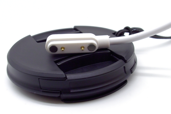
A magnetic cable changes the load path. The device-side interface can be designed as a flat or shallow connector surface, while the cable disconnects when the pulling force exceeds the magnetic retention force.
This can reduce several common mechanical risks:
- repeated insertion and removal of the device receptacle;
- side loading caused by an angled cable;
- damage when the cable is pulled suddenly;
- wear caused by users forcing a plug into the wrong position;
- PCB stress from a damaged or bent connector shell;
- downtime caused by replacing a device-mounted port.
The benefit is greatest when the device is charged frequently, handled by multiple operators or used in an environment where the cable may be pulled accidentally.
Applications That Benefit from Controlled Breakaway
Custom magnetic USB cables are often considered for:
- handheld medical and diagnostic devices;
- wearable electronics;
- portable scanners and data terminals;
- industrial measurement instruments;
- charging docks for sensors and IoT devices;
- hospital bedside equipment;
- shared charging stations;
- equipment used around moving operators or vehicles.
In these applications, controlled breakaway can be more important than maximum holding force. The cable should remain connected during normal use but disconnect before the load damages the device.
1. Breakaway Force Must Be Designed as a Window
The magnetic retention force should not simply be “as strong as possible.” It must remain within a useful operating window.
The lower limit is determined by the force required to maintain:
- pogo pin compression;
- stable electrical contact;
- normal cable movement;
- device vibration;
- the weight of the cable head;
- any sealing or gasket compression.
The upper limit is determined by:
- acceptable user separation force;
- device weight;
- housing strength;
- PCB support;
- the required breakaway behavior;
- the maximum load allowed before the device moves or falls.
Magnetic retention must be high enough to maintain stable pogo pin contact during normal use, but low enough to release before cable pull damages the device or drags the device from its position.
A cable for a lightweight wearable may need a much lower breakaway force than a cable used on an industrial dock. The force should therefore be specified for the application rather than copied from an existing connector.
2. The Device-Side Interface Must Carry the Mechanical Load Safely
Even with magnetic breakaway, the device-side connector still experiences compression, side load and repeated docking. The connector should be supported by the enclosure rather than relying only on PCB solder joints.
Design features may include:
- housing shoulders that transfer force into the enclosure;
- locating posts;
- mechanical retaining features;
- reinforced PCB mounting areas;
- overmolded or insert-molded connector modules;
- controlled clearances around the magnetic head;
- guide walls that limit side loading.
A flat magnetic interface can reduce deep-port damage, but it should not be installed as an unsupported PCB component if the cable will be connected and disconnected frequently.
3. Pogo Pin Compression Controls Electrical Stability
Magnetic attraction brings the cable head and device interface together, but the pogo pins provide the actual electrical contact.
Each pogo pin must operate inside its recommended working-stroke range. If compression is too low, contact force may be insufficient. If compression is too high, the pogo pin may bottom out, increase wear or apply excessive load to the housing.
The tolerance stack should include:
- pogo pin installed height;
- mating-pad height;
- plastic housing dimensions;
- magnet position;
- PCB thickness and flatness;
- overmolding variation;
- adhesive thickness;
- enclosure assembly tolerance.
| Compression condition | Possible result |
|---|---|
| Too little compression | Unstable contact, increased resistance or charging interruption. |
| Nominal compression | Contact remains inside the intended force and stroke range. |
| Too much compression | Bottoming, excessive wear, housing stress or PCB load. |
| Uneven compression | Different contact resistance or current sharing between pins. |
4. Pin Count Must Match the Required Function
The number of contacts depends on what the cable must do.
Two-pin magnetic USB cable
A two-pin design is commonly used for:
- positive power;
- ground.
This architecture is suitable when the cable is used only for charging or low-complexity power delivery.
Three- or four-pin design
Additional contacts may be used for:
- connector detection;
- temperature sensing;
- basic communication;
- device identification;
- separate charging control.
Multi-pin design
More contacts may support combined power, ground and selected data functions. However, high-speed data should not be assumed from the pin count alone.
USB data performance depends on:
- signal-pair layout;
- ground return;
- pin spacing;
- cable construction;
- shield termination;
- impedance control;
- connector transition geometry.
A magnetic connector intended for USB 2.0, USB 3.x or USB Type-C functions requires a dedicated electrical design and validation plan. A cable with a USB-C plug on one end is not automatically compliant with every USB-C power or data mode.
5. Wire Gauge and Cable Construction Determine Power Performance
A custom magnetic USB cable should be designed around the complete current path, not only the pogo pin rating.
The path includes:
- USB plug contacts;
- cable conductors;
- solder or crimp joints;
- PCB or internal cable-head traces;
- pogo pins;
- mating pads;
- device-side PCB traces.
Voltage drop and temperature rise depend on the resistance of every section. Important cable parameters include:
- wire gauge;
- conductor material;
- cable length;
- number of parallel power conductors;
- shield construction;
- insulation material;
- operating temperature;
- bending requirement.
Longer cables and smaller conductors generally create more voltage drop. For a charging cable, this can reduce the voltage reaching the device even when the connector itself has acceptable resistance.
Questions to define before selecting the wire
- What is the continuous current?
- What is the peak current?
- What is the allowable voltage drop?
- What is the cable length?
- Will the cable be bundled or enclosed?
- What ambient temperature is expected?
- How flexible must the cable be?
- Is repeated bending concentrated near the connector head?
6. Strain Relief Often Matters More Than the Outer Cable Diameter
Cable failures frequently occur near the connector head, where repeated bending concentrates stress at the transition between the flexible cable and rigid overmold.
A durable design should control this transition through:
- an appropriate bend radius;
- gradual stiffness transition;
- internal cable anchoring;
- overmold length;
- soft strain-relief geometry;
- controlled conductor routing;
- reinforcement where required.
A thicker overmold is not automatically more durable. If the transition is too stiff, the bending point may simply move farther down the cable and create a new fatigue location.
7. Hot-Plug Behavior Must Be Evaluated
Magnetic cables are often connected while the USB power source is already energized. During approach or separation, contacts may engage at different times or slide briefly across the mating pads.
This can create:
- contact bounce;
- inrush current;
- small electrical arcs;
- unstable device detection;
- temporary connection between unintended pads;
- surface discoloration or wear.
Possible control methods include:
- ground-first contact sequencing;
- a dedicated detection contact;
- current-limited start-up;
- pre-charge circuitry;
- recessed power contacts;
- mechanical guides that reduce sliding;
- software delay before enabling the main load.
The cable should not be described as hot-plug capable unless the contact sequence and electrical protection have been tested in the final device architecture.
8. Magnetic Alignment Does Not Replace Mechanical Guidance
Magnets can pull the cable head toward the device, but they do not always control the final position accurately enough by themselves.
A stable interface may also require:
- locating walls;
- recessed mating pockets;
- asymmetrical housing geometry;
- guide pins;
- large enough contact pads;
- controlled lateral clearance;
- anti-rotation features.
Mechanical guidance becomes more important as pin count increases. A two-pin charging cable may tolerate a simpler layout, while a multi-pin power-and-data cable needs stronger control of orientation and positional tolerance.
9. Metallic Debris Must Be Considered
Permanent magnets can attract iron-containing particles. In workshops, factories or service environments, small metal fragments may collect around the connector face.
Metallic debris can:
- bridge adjacent contacts;
- prevent full mating;
- scratch plated surfaces;
- increase contact resistance;
- change the magnetic gap;
- create intermittent operation.
Possible controls include:
- recessed contacts;
- insulating ribs;
- larger spacing between power contacts;
- cleaning instructions;
- protective caps;
- connector orientation that discourages debris collection;
- current limiting and fault detection.
10. A Custom Magnetic USB Cable Is Not Always the Best Choice
A conventional USB cable may remain more suitable when:
- a standardized user-replaceable cable is required;
- the connection must remain mechanically locked;
- high-speed USB data must meet a standard interface without custom validation;
- the operating environment contains heavy metallic debris;
- the device cannot accommodate magnets;
- the application requires a very low-cost cable;
- the device is connected only a few times during its lifetime;
- the cable must support multiple third-party chargers and accessories.
The correct decision depends on whether reduced port wear, blind docking and breakaway behavior provide enough value to justify a custom interface.
Custom Magnetic Cable vs. Conventional USB Cable
| Design factor | Custom magnetic USB cable | Conventional USB cable |
|---|---|---|
| Device-port insertion wear | Can reduce direct insertion cycles at the device interface. | The device receptacle experiences every mating cycle. |
| Cable pull | Can disconnect at a designed breakaway force. | Load may transfer into the plug, receptacle or PCB. |
| Interchangeability | Usually requires a dedicated cable and device interface. | Standard USB cables are widely available. |
| Blind connection | Magnetic attraction can simplify one-handed docking. | Usually requires visual or tactile alignment. |
| Data capability | Must be designed and validated for the required protocol. | Standard-compliant cables may simplify compatibility. |
| Development effort | Requires custom mechanical, electrical and cable validation. | Can often use an existing standard receptacle. |
Validation Plan Before Mass Production
A custom magnetic USB cable should be tested as a complete assembly, including both the cable and the device-side connector.
| Test | What to verify |
|---|---|
| Retention and breakaway | Cable remains connected during normal use and disconnects before damaging the device. |
| Contact resistance | Resistance remains within the approved limit before and after durability testing. |
| Voltage drop | The complete cable delivers sufficient voltage at the required current. |
| Temperature rise | Cable, connector head and contacts remain within the agreed temperature limit. |
| Bending test | Conductors and strain relief survive repeated bending near the connector head. |
| Cable pull test | Internal anchoring and overmolding resist axial cable pull. |
| Mating-cycle test | Contacts, plating, magnets and housing remain functional after repeated docking. |
| Hot-plug test | Connection and separation do not create unacceptable arcing, reset or contact damage. |
| Misalignment test | Offset or angled approaches do not bridge unsafe contacts. |
| Data test | Required communication mode remains stable across cable length and mating cycles. |
Information Required for a Custom Cable Project
Before requesting a custom magnetic USB cable, provide:
- USB connector type on the source side;
- charging-only or charging-and-data requirement;
- continuous and peak current;
- required voltage;
- data protocol and speed;
- pin count and pin assignment;
- cable length;
- preferred wire gauge;
- jacket material and flexibility requirement;
- available device-side connector area;
- mating direction;
- required retention or breakaway force;
- working environment;
- mating-cycle target;
- expected annual quantity;
- 2D drawings, 3D models or device samples.
These inputs allow the magnetic connector, cable conductor, overmold, strain relief and electrical protection to be evaluated as one design.
Frequently Asked Questions
Can a custom magnetic USB cable completely prevent port damage?
No. It can reduce repeated insertion and may disconnect during a cable pull, but the device-side connector and enclosure still require sufficient mechanical support and validation.
Does every magnetic USB cable support data transfer?
No. Many two-pin magnetic cables are designed only for charging. Data transfer requires additional contacts and a suitable signal, ground, cable and shielding design.
Can a magnetic cable support USB-C fast charging?
Potentially, but the cable must be designed around the required USB-C power architecture, identification, current, contact resistance and protection requirements. A USB-C plug alone does not ensure compatibility with every fast-charging mode.
How strong should the magnets be?
The magnets should maintain contact during normal use while allowing the cable to release before damaging or moving the device. The correct force depends on spring load, cable weight, device mass and the application.
Can several pogo pins be connected in parallel for higher current?
Yes, but current sharing should be verified. Differences in compression, contact resistance, soldering and PCB routing can cause uneven current distribution.
Why does a magnetic cable become warm?
Possible causes include excessive current, small wire conductors, long cable length, high contact resistance, poor mating compression or an inadequate solder joint. Temperature-rise testing should cover the complete cable assembly.
Are magnetic USB cables suitable for industrial environments?
They can be, but the design should consider vibration, cable pull, contamination, metallic debris, chemical exposure, cleaning methods and retention-force requirements.
Conclusion
A custom magnetic USB cable can reduce repeated wear at the device interface, simplify docking and provide controlled breakaway during accidental cable pull. These advantages are most valuable in devices that are charged frequently or used in environments where a damaged port creates significant downtime.
The cable must still be engineered as a complete system. Magnetic force, pogo pin compression, cable gauge, voltage drop, strain relief, overmolding, hot-plug behavior and device-side mechanical support all affect reliability.
CTP supports custom development of magnetic cable assemblies, magnetic pogo pin connectors, pogo pin connector assemblies and individual pogo pins.
For a custom cable project, submit your connector type, pin map, current, cable length, data requirements, available space and device drawings through our Get a Quote & Samples page. The magnetic head, cable structure and device-side interface can then be reviewed together before prototype development.
CTP ENGINEERING PATHS
Choose the right path for your project
Move from application requirements to a connector pair, a data-capable cable assembly, or a charging cable configuration. Final specifications are confirmed against an approved drawing and project validation plan.
Magnetic Connectors
Connector geometry, pin layout, mechanical integration and OEM/ODM review.
Engineering overview → 02Magnetic Data Cables
Power and signal allocation, cable exit, interface selection and assembly review.
Cable engineering → 03Magnetic Charging Cables
Browse the complete cable catalog and shortlist a starting structure for customization.
View cable catalog →