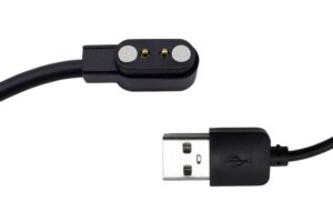
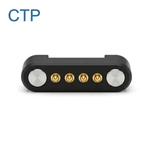
A magnetic pogo pin cable is a detachable cable assembly that combines magnets for alignment and retention with spring-loaded contacts for electrical power, detection or data transfer. It can reduce repeated insertion into a conventional device receptacle, but the cable alone does not determine whether the interface is reliable.
The complete system includes the cable head, pogo pins, magnets, mating pads, device-side module, PCB or FPC termination, protection circuit and mechanical enclosure. Each part must be designed together.
For commercial and industrial equipment, the most useful architecture is often not simply a “stronger magnetic cable.” It is a controlled interface family in which the correct cable mates with the correct device, power remains disabled during unsafe contact conditions and the device-side contact module can be replaced without removing the main PCB.
A magnetic pogo pin cable can reduce wear on a conventional plug-in port when the magnetic interface becomes the regularly replaced service connection. To achieve this benefit, engineers must control cable compatibility, breakaway direction, contact sequencing, cable-head strain relief and the replacement method for the device-side contact module.
What Problems Can a Magnetic Pogo Pin Cable Solve?
A magnetic cable may be useful when a device is connected and disconnected frequently, used in a shared environment or exposed to accidental cable pull.
Typical applications include:
- portable medical or diagnostic equipment;
- retail terminals and handheld scanners;
- industrial tablets and data collectors;
- wearable and personal-care devices;
- charging cradles for shared equipment;
- portable test instruments;
- smart locks and access-control devices;
- removable sensor or battery modules;
- equipment requiring a shallow external contact surface.
The architecture may reduce several system-level risks:
- repeated wear on a conventional receptacle;
- damage caused by pulling a rigid plug sideways;
- difficulty connecting the cable with one hand;
- repair cost when the original PCB-mounted port fails;
- deep openings that are difficult to integrate into a sealed enclosure.
These benefits are conditional. Incorrect pin mapping, exposed live contacts, excessive magnetic force or an unsuitable breakaway direction can introduce new problems.
A Magnetic Cable Is an Interface System, Not Only a Cable
The cable should be specified together with the device-side connection.
| System element | Primary function | Main engineering concern |
|---|---|---|
| Cable head | Holds magnets, contacts, PCB and cable termination. | Size, strain relief, overmolding and pull-load transfer. |
| Pogo pins or contact pads | Transfer power, detection or signals. | Compression, contact resistance, current and contamination. |
| Magnets | Assist alignment and retain the connection. | Polarity, air gap, retention range and debris attraction. |
| Device-side module | Provides the mating surface and connects to the device electronics. | Replaceability, sealing, mounting and PCB protection. |
| Protection circuit | Controls power enable and abnormal current. | Partial mating, reverse contact, hot plugging and short circuits. |
| Cable conductors | Carry current or signals between the source and connector head. | Wire gauge, flex life, length, shielding and voltage drop. |
1. Choose the Correct Magnetic Cable Architecture
Magnetic cables can be divided into several architectures.
Integrated device-side contact module
The device contains a permanently mounted magnetic contact module. The cable head attaches directly to it.
This structure is suitable when:
- the magnetic interface is designed into the enclosure from the beginning;
- the device does not require compatibility with a standard external plug;
- the contact module can be sealed or mechanically supported;
- the project controls both the cable and device design.
Replaceable device-side adapter
A small adapter remains connected to an existing device port, while the magnetic cable connects to the adapter.
This approach may reduce repeated direct insertion, but it also introduces:
- additional electrical transitions;
- added mechanical leverage on the original port;
- a removable part that can be lost;
- possible third-party compatibility problems;
- limited sealing around the original receptacle.
Dock-side magnetic cable
The cable head is fixed inside a stand, dock or fixture. The device is placed against it rather than manually attaching the cable.
This can be useful for shared equipment because the docking position and cable movement are more controlled.
Double-ended magnetic cable
Both ends use a magnetic interface. This may support modular equipment, but it also doubles the number of exposed interfaces and compatibility risks. Each side must be keyed and identified correctly.
2. Design a Cable Family That Prevents Cross-Mating
Enterprise equipment may include several products with similar-looking magnetic cables but different voltage, current or pin assignments.
A cable that physically attaches to the wrong device may create:
- reverse polarity;
- incorrect voltage application;
- power applied to a signal circuit;
- unsupported charging current;
- communication errors;
- damage to an accessory or device.
Compatibility should therefore be controlled mechanically and electrically.
Mechanical keying options
- asymmetrical connector shape;
- different contact spacing;
- offset magnets;
- different connector-head dimensions;
- guide ribs or locating recesses;
- different circular key positions;
- male and female housing features.
Magnetic keying options
Magnet polarity can help reject an incorrect orientation, but polarity alone should not be relied on when an incorrect electrical connection could damage the device.
Electrical identification
An additional contact or resistor-identification circuit can allow the device to verify the cable or accessory before enabling full power.
Two cables that are electrically incompatible should not share an identical mechanical interface unless the device includes a verified method of identifying and rejecting the wrong cable.
3. Assign the Pin Map Before Choosing the External Shape
The connector pin count should be derived from the circuit requirements.
Two-pin cable
A basic two-pin layout may provide:
- positive power;
- ground.
This is simple, but it provides no dedicated contact for cable detection, identification or temperature monitoring.
Three- or four-pin cable
Additional contacts may provide:
- connector detection;
- cable or accessory identification;
- temperature sensing;
- basic control communication;
- separate protective or functional ground.
Multi-pin cable
A multi-pin magnetic cable may combine power, control and data. As pin count increases, the design must review:
- power-to-signal separation;
- ground-return allocation;
- incorrect offset mating;
- contact sequencing;
- signal return paths;
- contact compression across the full array.
4. Decide Which Side Contains the Spring-Loaded Contacts
The pogo pins may be installed on the cable side or the device side.
| Architecture | Potential advantage | Main concern |
|---|---|---|
| Pogo pins in the cable head | The spring contacts are replaced when the cable is replaced. | Cable-head size, termination and contact exposure. |
| Pogo pins in the device | Cable head may use simple flat pads. | Worn or stuck pogo pins may require device repair. |
| Replaceable device-side pogo module | The device keeps a modular service part instead of exposing the main PCB. | Requires additional mounting, gasket and internal connection space. |
For equipment with long service life, placing wear-prone contacts in a replaceable cable or replaceable device module may reduce repair cost.
5. Keep Exposed Contacts De-Energized When Possible
Magnetic connectors often use shallow or exposed contacts. The source side should not automatically remain energized whenever it is disconnected.
Potential risks include:
- metal objects bridging adjacent contacts;
- liquid contamination;
- incorrect cable attachment;
- partial mating;
- contact with conductive work surfaces;
- surface damage caused by arcing.
Possible protection methods
- keep the main power path disabled until correct mating is detected;
- use current limiting during initial contact;
- add short-circuit protection;
- recess the main power pads;
- use insulating barriers between contacts;
- assign the exposed cable side according to source and sink safety;
- de-energize the interface before separation where possible.
6. Define the Contact Sequence
During angled mating, the contacts may not engage simultaneously. A connector can therefore be electrically connected before it reaches full mechanical engagement.
A controlled sequence may use:
- a longer ground contact;
- a dedicated detection contact;
- a shorter main-power contact;
- different mating-pad heights;
- electronic delay before power enable;
- pre-charge for capacitive loads.
Example sequence
- Ground contact engages.
- Cable-detection contact becomes active.
- The device identifies the expected cable.
- The main power path is enabled.
- The charging or operating current increases to the required level.
The sequence should also be checked during slow connection, partial mating and incorrect angular approach.
7. Design Breakaway Force by Direction
Magnetic cable retention should not be described by one force value without defining the direction of the test.
A connector may behave differently under:
- straight axial pull;
- side pull;
- peeling from one edge;
- torsion;
- cable bending near the connector head.
A cable that requires substantial axial force may still release easily when peeled from one edge. This can be useful for accidental cable pulls, but unsuitable when the connector must remain engaged during device movement.
Breakaway-force inputs
- device mass;
- expected cable pull direction;
- cable stiffness;
- total pogo pin spring load;
- user handling;
- mounting orientation;
- required retention during normal operation;
- maximum acceptable load on the device housing.
Breakaway performance should be tested with the final cable length and routing rather than with an isolated connector head.

8. Transfer Cable Pull into the Housing, Not the Solder Joints
The cable head should include a load path that transfers pull and bending forces into the molded or mechanical housing.
The solder joints, PCB pads and pogo pin terminations should not carry the full cable load.
A cable-head load path may include:
- conductor strain relief;
- outer-jacket anchoring;
- overmold ribs;
- crimp sleeves;
- mechanical clamps;
- potting around the termination area;
- a gradual flexible transition behind the rigid connector head.
Common cable-head problems
- jacket separation from the overmold;
- conductor breakage near the solder joint;
- PCB movement inside the connector head;
- cracks at the rigid-to-flexible transition;
- water entering through the cable exit;
- torsion transferred into the contact assembly.
9. Do Not Make the Strain Relief Too Rigid
A rigid strain relief can move the bending point farther down the cable rather than removing the stress. The transition should distribute bending over a suitable length.
Strain-relief design should consider:
- cable outside diameter;
- jacket material;
- conductor stranding;
- minimum bend radius;
- expected bending direction;
- number of flex cycles;
- working temperature;
- cleaning chemicals;
- overmold-material compatibility.
10. Make the Device-Side Port Replaceable
A magnetic interface can reduce direct wear on a conventional port, but the device-side contact surface may still become damaged, contaminated or corroded.
For equipment with long service life, the contact interface can be designed as a separate replaceable module.
Possible replaceable-port structures
- screw-mounted connector module;
- small daughterboard connected by FPC;
- board-to-board removable contact module;
- sealed cable pigtail connected internally;
- replaceable enclosure insert containing contacts and magnets.
Benefits of modular replacement
- the main PCB does not need to be replaced after contact damage;
- service time can be reduced;
- the port can be inspected separately;
- gaskets and contact surfaces can be replaced together;
- future revisions may be introduced without redesigning the complete device.
Service-module design questions
- Can technicians access the mounting screws?
- Does replacement require soldering?
- Can the module be installed in the wrong orientation?
- Is a new gasket required after replacement?
- Does the replacement procedure change contact compression?
- How is the new module tested after service?
11. Select the Cable Conductors from the Complete Load
The pogo pins are only one part of the current path. Cable conductors and terminations also contribute to voltage drop and temperature rise.
Define:
- continuous current;
- peak current and duration;
- cable length;
- acceptable voltage drop;
- ambient temperature;
- number of power conductors;
- conductor stranding;
- flex requirements;
- enclosure and overmold heat retention.
Increasing conductor size may reduce resistance but also makes the cable stiffer. Cable stiffness can increase peeling force at the magnetic interface and transfer more movement into the device.
The electrical and mechanical effects of wire selection should therefore be reviewed together.
12. Separate Charging-Only and Data-Capable Cable Claims
A magnetic cable that transfers DC power should not automatically be described as a USB data cable.
Data capability depends on:
- the required protocol;
- pin count;
- signal and return allocation;
- connector-head PCB routing;
- cable construction;
- shield termination;
- contact symmetry;
- channel validation.
| Cable function | Primary design focus |
|---|---|
| Charging only | Current, voltage drop, temperature, polarity and contact sequencing. |
| Charging plus identification | Adds detection or resistor identification before power enable. |
| Charging plus low-speed data | Requires defined signal contacts, return paths and functional testing. |
| High-speed data | Requires protocol-specific geometry, impedance and channel validation. |
13. Control Magnet Position and Polarity in Production
Magnet assembly affects orientation, retention and compatibility.
Potential production problems include:
- reversed polarity;
- magnet installed at the wrong depth;
- magnet movement during adhesive curing;
- unequal magnet spacing;
- mixed magnet dimensions;
- adhesive contamination on the contact face;
- retention-force variation between lots.
Recommended production controls
- polarity-controlled assembly fixtures;
- functional mating with an approved counterpart;
- magnet-position inspection;
- adhesive-dispensing control;
- retention-force measurement;
- clear cable-family identification.
14. Plan for Field Identification and Cable Management
In shared-device or enterprise deployments, several visually similar cables may be present in the same workplace.
Field controls may include:
- permanent cable labels;
- model or voltage marking;
- color-coded connector heads;
- different keyed interfaces;
- serial or batch codes;
- approved-cable lists;
- replacement-date records;
- storage covers for exposed contact heads.
Color alone should not be the only control when the wrong cable could damage the device.
15. Define Replacement Criteria Before Deployment
Magnetic cables should be treated as replaceable wear items when used frequently.
Possible replacement indicators include:
- damaged or cracked overmolding;
- exposed conductors;
- loose cable-head components;
- increasing voltage drop;
- abnormal connector temperature;
- stuck pogo pin plungers;
- significant contact-surface wear;
- reduced or inconsistent retention force;
- repeated connection retries;
- visible metallic debris that cannot be removed safely.
Replacement should be based on observed condition and application-specific testing rather than one universal cycle number.
Magnetic Pogo Pin Cable Validation Matrix
| Validation area | Recommended evaluation |
|---|---|
| Correct mating | Straight, angled, partial and reversed mating attempts. |
| Wrong-cable mating | Verify incompatible cables cannot create an unsafe electrical connection. |
| Retention and breakaway | Axial, side, peel and torsional separation forces. |
| Cable pull | Straight pull and angular pull on the final cable assembly. |
| Cable flex | Repeated bending at the connector-head transition and normal working locations. |
| Electrical resistance | Complete cable resistance and connector voltage drop before and after aging. |
| Temperature rise | Cable head, conductors and device-side contacts under continuous load. |
| Hot-plug behavior | Inrush current, sequencing, arcing and contact condition after repeated mating. |
| Contamination | Dust, metallic particles, moisture, oil and approved cleaning procedures. |
| Service replacement | Port-module replacement time, orientation control, sealing and post-service test. |
When a Magnetic Pogo Pin Cable May Not Be Suitable
A conventional cable or standardized connector may be more appropriate when:
- third-party cable compatibility is required;
- the interface must remain positively locked under continuous load;
- the device cannot keep exposed contacts de-energized;
- the environment contains uncontrolled metallic debris;
- a standardized high-speed protocol connector is mandatory;
- the connection remains permanently installed;
- the magnetic field may interfere with nearby components or processes;
- the product cannot support keyed cable-family management;
- the device-side module cannot be mechanically supported.
Information Required for a Custom Magnetic Cable Project
To evaluate a custom magnetic pogo pin cable, provide:
- device type and application;
- charging-only or charging-and-data requirement;
- pin count and pin assignment;
- continuous and peak current;
- operating voltage;
- acceptable voltage drop;
- signal protocol and data rate;
- cable length;
- preferred cable diameter and flexibility;
- device-side available space;
- connector mating direction;
- desired retention and breakaway behavior;
- possible wrong-cable combinations;
- hot-plug and power-sequencing requirements;
- environmental and cleaning conditions;
- expected mating and cable-flex cycles;
- device-side replacement strategy;
- prototype quantity and production forecast;
- 2D drawings, 3D models and electrical diagrams.
Frequently Asked Questions
What is a magnetic pogo pin cable?
It is a cable assembly that uses magnets for alignment and retention and spring-loaded contacts for conductive power or signal transfer.
Can a magnetic cable prevent device-port damage?
It can reduce repeated insertion into a conventional receptacle and can release under selected cable-pull conditions. The result depends on the breakaway geometry, device-side mounting and complete cable design.
Should the pogo pins be placed in the cable or the device?
Placing the pogo pins in the cable makes them replaceable with the cable. Placing them in a removable device-side module can also support serviceability. The correct choice depends on space, sealing and repair strategy.
Can two magnetic cables with the same shape use different voltages?
They should not share an unrestricted interface unless the system includes reliable mechanical keying and electrical identification that prevents unsafe cross-mating.
Does a magnetic cable need a detection pin?
Not every design requires one, but a detection or identification contact can help keep the main power disabled until correct mating is confirmed.
Is magnetic charging the same as wireless charging?
No. A magnetic pogo pin cable transfers power through conductive contacts. The magnets provide mechanical alignment and retention.
Can a magnetic pogo pin cable carry USB data?
Potentially, but data performance depends on the pin arrangement, cable construction, signal return, PCB transition and protocol-specific validation. A charging cable should not automatically be described as a USB data cable.
Does stronger magnetic force provide better port protection?
Not necessarily. Excessive retention can transfer more force into the device and reduce the intended breakaway behavior. Retention should be tested in the expected pull directions.
Can the device-side magnetic port be waterproof?
It can be integrated into a sealed device module. The final protection level depends on the enclosure, gasket, molding, cable entry and assembled test conditions.
How should magnetic cables be maintained in enterprise deployments?
Use approved cable families, inspect contact surfaces and strain relief, remove contamination with an approved method and replace cables showing abnormal resistance, heating, damage or repeated connection failures.
Conclusion
A magnetic pogo pin cable can provide more than a convenient charging connection. When designed as a controlled interface system, it can move the frequently replaced wear component away from the main device PCB and into a serviceable cable or contact module.
The design should prevent incompatible cables from mating, keep exposed power contacts in a safe state and control the order in which detection, ground and power contacts engage. Cable-head strain relief should transfer pull into the housing rather than the solder joints, while breakaway behavior should be evaluated in axial, side and peel directions.
For long-life enterprise equipment, the device-side contact module should also be considered a service part. A replaceable connector board, FPC module or enclosure insert can reduce repair time when the contacts, gasket or magnets eventually require maintenance.
CTP supports custom development of magnetic pogo pin cable assemblies, magnetic pogo pin connectors, pogo pin connector assemblies and individual pogo pins.
For a custom cable project, submit your pin map, voltage, current, cable length, device-side space, wrong-cable risks and service strategy through our Get a Quote & Samples page. The cable head, device-side port and protection architecture can then be evaluated together.
CTP ENGINEERING PATHS
Choose the right path for your project
Move from application requirements to a connector pair, a data-capable cable assembly, or a charging cable configuration. Final specifications are confirmed against an approved drawing and project validation plan.
Magnetic Connectors
Connector geometry, pin layout, mechanical integration and OEM/ODM review.
Engineering overview → 02Magnetic Data Cables
Power and signal allocation, cable exit, interface selection and assembly review.
Cable engineering → 03Magnetic Charging Cables
Browse the complete cable catalog and shortlist a starting structure for customization.
View cable catalog →